

When dealing with errors in firmware, one encounters formal explanations of concepts like “undefined behavior,” “storage duration,” “variable lifetime,” “initialization,” and “dereferencing”, whether scrolling Stack Overflow, arguing with your LLM of choice, or studying C standards at university, or discussing over an implementation detail with a colleague. These concepts are presented theoretically, rigorously, as abstract computer science. Yet when a student tries to apply them to a physical machine, confusion emerges: What does it actually mean to “destroy” a variable? What does the C standard truly mean by “undefined”? The gap between theory and practice remains.
To bridge this gap, I’ll show a real bug that interconnects most of these concepts simultaneously. This bug emerged while developing an I2C device driver and is a very simple one, actually is due to a single typo. Yet this tiny error cascades through the entire system, exposing fundamental violations of variable lifetime and memory safety. By carefully unwrapping this one bug, we’ll see how these abstract theoretical concepts manifest as concrete failures in a physical device.
As a final demonstration of how subtle these errors can be, and how consequential, this bug will be exploited to “mischievously manipulate” the hardware, causing an LED to blink through a simple stack exploit.
Unexpected I2C data
It all starts with a function i2c_test() that demonstrates how to use this driver, but also inadvertently exposes a critical vulnerability. Briefly explaining the code below, it allocates a 32-byte buffer on the stack, validates the I2C interface status, and registers five event callbacks that will execute at different stages of the I2C transaction. It then prepares the data by setting the first byte to 0xAA and initiates the I2C transmission to a device address 0x61, returning an error code to indicate success or failure. On the surface, this looks correct.
Here the function just described:
int8_t i2c_test(conf_i2c_e i2c_enumerator){ int8_t err = 0; uint8_t buff[32]; if (I2c_hal_status(i2c_enumerator) == I2C_HAL_NOTIFY_ERR) { err = -1; } else { I2c_hal_ISR_callback_register(i2c_enumerator, I2C_HAL_ISR_T_TX, i2c_tx_test); I2c_hal_ISR_callback_register(i2c_enumerator, I2C_HAL_ISR_T_ADDR, i2c_adx_test); I2c_hal_ISR_callback_register(i2c_enumerator, I2C_HAL_ISR_T_START, i2c_start_test); I2c_hal_ISR_callback_register(i2c_enumerator, I2C_HAL_ISR_T_END, i2c_btf_test); I2c_hal_ISR_callback_register(i2c_enumerator, I2C_HAL_ISR_T_STOP, i2c_stop_test); buff[0] = 0xaa; // <-- the ("faulty"?) test byte /* just send one byte to address 0x61 (note: r/w bit is not visible in the address) */ if (I2c_hal_master_start(i2c_enumerator, I2C_HAL_WR_STOP, I2C_DEV_ADDR, 1, buff) == I2C_HAL_NOTIFY_OK) { err = 0; } else { err = -1; } } return err;}
The problem emerges when we consider what happens during the asynchronous interrupt handling that follows. The actual I2C driver logic executes inside i2c_hal_i2c1_isr(), where it retrieves bytes from the buffer using the pointer stored into buffp, increments it with each transmission, and writes data to the I2C data register (DR). This buffer access occurs asynchronously during interrupt handling, potentially long after i2c_test() has returned.
This is the ISR code which access the 32-bytes buffer previously allocated:
static void i2c_hal_i2c1_isr(){[...] if ((i2c_hal_conf_buff[I2C_HAL_ENUM_I2C1].periph->SR2 & I2C_SR2_MSL)) { // master specific [...] // the user callback registered i2c_hal_ISR_ma_te_cb[I2C_HAL_ENUM_I2C1](i2c_hal_conf_buff[I2C_HAL_ENUM_I2C1].i2c); [...] // the data transmission from the 32 bytes buffer pointer i2c_hal_conf_buff[I2C_HAL_ENUM_I2C1].periph->DR = (uint32_t)* (i2c_hal_conf_buff[I2C_HAL_ENUM_I2C1].buffp + (i2c_hal_conf_buff[I2C_HAL_ENUM_I2C1].cnt++)); [...] }. // end I2C_SR2_MSL [...]} // end i2c_hal_i2c1_isr()
Here lies the catastrophic flaw: when i2c_test() returns, the stack frame containing buff[32] ceases to exist and its memory becomes available for reuse by whatever code executes next, since the CPU repurposes that region for new variables, or even ISR internal ones when we are inside the i2c_hal_i2c1_isr().
The ISR then dereferences a pointer that no longer refers to a valid object and instead reads whatever happens to live in that reclaimed stack space, producing not randomness but leftover data from prior stack activity. This represents an example of undefined behavior caused by an expired variable lifetime: the C standard provides no guarantees once a pointer outlives its object, and in this case the stale pointer feeds garbage directly into the I2C data register, corrupting the transmission and turning a theoretical lifetime violation into a very real hardware-level failure.
And that’s exactly why during the test I see on the bus the following:
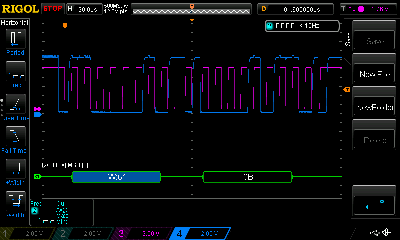
Values like 0x0B make no sense when 0xAA was the intended byte. While correcting the bug is straightforward, here we want to understand why we were sending this specific wrong value, since it will form the basis of our later stack exploit. This requires exploring the programming concepts like variable lifetime or storage duration, happening in this example described.
The storage duration
The problem is related to the concept of variable lifetime, or storage duration. We know this term because it describes a behavior defined in the C standard: the storage duration of a given variable is decided with it’s declaration. With non blocking code like an I2C interrupt based driver, if we pass a pointer to another function (here an ISR) then the variable must still exist when the code reference to it, and therefore it must be declared as static. Without it, we dealing with daggling pointers.
In fact, checking the addresses of the “faulty” byte we see:
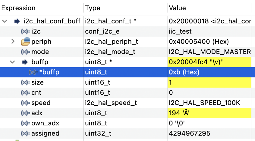
The byte 0x0B that can be seen in Figure 2 is exactly what is mistakenly sent, and is located at the address 0x20004FC4 which is the base pointer of the buffer. After correcting the duration with the use of static, when we check the memory content, this time is different:
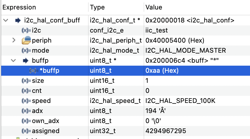
The byte 0xAA sent is now sent, but interestingly is also located at a completely different adress being now 0x200006C4.
If we put closer attention, we noticed something more. Those addresses are spaced 18kB apart (0x4FC4 – 0x06C4), basically the entire RAM memory of the MCU. To understand this aspect and what this means, we need to explore how the static and automatic variables are implemented and translated into machine level code.
How automatic (non-static, local) variables are created
To understand what is going on, we need to understand how these addresses shown before are what they are. To do so, let’s see the linker file:
/* Memories definition */MEMORY{ RAM (xrw) : ORIGIN = 0x20000000, LENGTH = 20K FLASH (rx) : ORIGIN = 0x8000000, LENGTH = 64K}
From this is clear that a variable is almost always put in RAM (technically, anything connected to the memory bus of the CPU, and the most practical system for this storage job is… a RAM memory device). But the data RAM is not generated from nowhere and it must come from non volatile memory (typically, the flash memory, ROM and so on).
In fact, the disassembly of a variable allocation starts with hardcoded instructions, with stack pointers and hardcoded numbers assigned for initialization:
disassemble /m i2c_test
Dump of assembler code for function i2c_test:
174	{
   0x08004038 <+0>:	push	{r7, lr}
   0x0800403a <+2>:	sub	sp, #56	@ 0x38
   0x0800403c <+4>:	add	r7, sp, #8
   0x0800403e <+6>:	mov	r3, r0
   0x08004040 <+8>:	strb	r3, [r7, #7]
175	  int8_t err = 0;
   0x08004042 <+10>:	movs	r3, #0
   0x08004044 <+12>:	strb.w	r3, [r7, #47]	@ 0x2f
176	  uint8_t buff[32];
The snippet before, allocates 56 bytes from the stack pointer, stores in R7 offsets from the SP and does any sort of manipulations that will be explained here.
To start noticing correspondences betweend the stack allocation and the actual memory in debug, we can plot the stack information just before entering the function:
x/32xb $sp
0x20004ff0: 0xf8 0x4f 0x00 0x20 0xf8 0x4f 0x00 0x00
0x20004ff8: 0xb8 0x4f 0x00 0x20 0xd3 0x07 0x00 0x08
And just after entering it:
x/32xb $sp
0x20004fb0: 0x0f 0x00 0x00 0x19 0x40 0x19 0x01 0x00
0x20004fb8: 0xc0 0x4f 0x00 0x20 0xc0 0x4f 0x00 0x00
The stack pointer is 64 bytes smaller! This includes in fact also the preamble of the function, made by 8 bytes of the R7 and LR combined.
To understand that, a drawing can help:
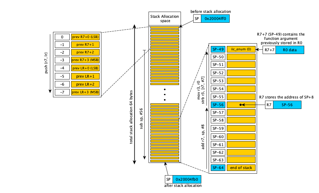
Entering the function, in the stack will be saved the previous value of LR and R7, containing the return addresses and the previous stack pointer, since these LR and R7 will be updated again inside this function. Note that the function begins at address 0x08004038 in the listing above, because this very 0x08004038 address was the target of a previous BL (branch with link) instruction that called our i2c_test(). And also, when a previous caller function wanted to call i2c_test() it used this specific address 0x08004038 as a parameter in the assembly because that was the address mapping the i2c_test() function. Ok, maybe this was a bit redundant, but is important to know where the functions are starting from and why, because in the push {r7, lr} seen in Figure 4 and therefore the listing, the data stored in it is by definition data of the caller (previous) function out of the current context, and is used as bread crumb for the CPU to return correctly where it was before entering the actual function.
Then, continuing the analysis of Figure 4, new stack space is allocated by decrementing SP pointer by additional 56 bytes (sub sp, #56). Now the new stack space is 64 bytes big. Then is established a frame pointer of 8 bytes above SP (add r7, sp, #8), to use the R7 to navigate into this 64 byte address space, usually for referencing local variables. Using R7 is better than SP since an internal CPU register like this can change only with explicit instructions and keeps the SP unchanged, making the while mechanism more reliable and simple at the expense of one CPU register.
Now because we want to understand local variables, we want to identify one of them as exercise. Let’s check the parameter passed into this function, initially (by definition of the arm-gcc compile) is stored in R0 when entering. To store the reference using R7, previously is used R3 as a holding register via (mov r3, r0), and then R3 data is copied into the address pointed by R7+7 with (strb r3, [r7, #7]). This data initially in R0 and moved to R7+7 contains the I2C enumerator (equal to 0 in this particular case). Note we can use R0 bypassing R3, but the code here is not optimized and compiler has preferences on registers use that might add some overhead. This handles only the parameter called iic_enum (equal 0), but for other local variables the addressing mechanism is the same.
Back to our value of interest, buff[], we know that is not initialized, and it is already allocated by default in the space within R7+12 and R7+44, since we identified in Figure 2 having &buff[0] = 0x20004FC4 and SP = 0x20004FB0. In fact the address of buff[] is not explicitly visible in the source, but is determined implicitly by the compiler when using relative addressing from the stack pointer. And the stack pointer changes, depending how the code is compiled and from where the function is called and depending what is going on in the software as a whole and so on. In this case, it is the SP (the end, 0x20004FB0), plus 8 (the R7), plus 12 (the R7+12).
This very last +12 was found in debug, but by only knowing the SP is also possible to identify the address of buff[] by checking where is performed the access to the first element to it, if available. It can be found strb r3, [r7, #12], where R3 has been previously loaded with 0xAA using movs r3, #170. Which is the value we wanted to send initially, 0xAA.
A legit question could be: why not write directly into the address pointed to by R7? The reason is that ARM Thumb instructions are limited to 16 or 32 bits and cannot encode arbitrary 32-bit immediates values containing the address to be used as data for the instruction. Therefore, the data value is placed in a register (R3) that can be represented by a simple op-instruction, while the base address remains in another (R7), resulting in the compact instruction pair 23aa and 733b with hardwired access to the register stored in them and no explicit 32-bit data or address visible in the opcodes:
buff[0] = 0xaa; // <-- the ("faulty"?) test byte
 800403e:	23aa      	movs	r3, #170	@ 0xaa
 8004040:	733b      	strb	r3, [r7, #12]
So, a local variable is nothing more than a value in a stack referenced by a register and eventually relative to the stack itself. So everytime the parameter iic_enum is needed, an instance of R7+7 appears, since the compiler will always use explicitly the offset “R7+7”, which corresponds to SP-49. Or the variable err = 0 stored in R7+47. In the same manner, the buff[] is accessed anytime we see an access with R7+12 to R7+44 indexing. For this reason, a local variable is not available in the map file and its address cannot be known at compile time. And therefore, deallocating the stack it means that the variable is “destroyed”, finishes it’s lifetime and eventual references to that memory area after that moment are either an error or a bug, since the access to those location will be from other memory context coming from other functions.
Since the compiler typically cannot detect accesses via pointers, like in the case of the reference to buff[], it will allows accesses to expired stack frames, and such access results in undefined behavior since the variables in that area are not considered valid anymore and can be used by other functions. In these scenarios, this manipulation must be done only on static variables.
How static variables are created
To appreciate the fundamental difference between a local and a static variable, now we can examine also how the static variable is created. In the I2C buffer example, using non-static variables was the source of the problem. Using a static keyword will allow the lifetime to last for the entire program, and hence, it’s address never become invalidated.
To do that, it must be stored somewhere else with it’s address resolved at compile time and be used in a safe RAM area. To know this address ahead, with the code re-compiled with the static keyword, the assembly changes. The buff[] is not anymore stored its value is stored in an instruction in FLASH. Let’s consider this listing:
 buff[0] = 0xaa; // <-- the ("faulty"?) test byte
 800403a:	4b11      	ldr	r3, [pc, #68] @ +0x44 (8004080 <i2c_test+0xa4>)
 800403c:	22aa      	movs	r2, #170	@ 0xaa
 800403e:	701a      	strb	r2, [r3, #0]
 [...]
 8004080:	200006ac 	.word	0x200006ac
The instruction ldr r3, [pc, #68] loads in RAM the initial value contained at the instruction in FLASH pointed out in the list file as 0x8004080, which contains the.word 0x200006c4. Must be noted that 0x800403A+0x44 (68 decimal) is 0x800407E, but the PC (program counter) evaluated will be the actual PC plus 4, giving 0x800407E+0x4 = 0x8004082, but here we are word aligned and so the last 2 bits will be set to 0, giving finally 0x8004080.R3 holds now the pointer 0x200006c4, and R2 contains the value 0xAA (#170) to be written at that address, and the final writing performed by strb r2, [r3, #0], where #0 is simply a null offset from the location pointed by R3, but the instruction requires this parameter anyway even if not necessary.
The values located at 0x8004080 are forming the literal pool, and is in fact typically placed after the function’s instructions and may point to any memory region, usually far from stack areas, if not by design to the opposite, like in this case, 18kB apart on a 20kB device, explaining the big difference in address between the watched variables in Figures 2 and 3. This is reflected in the .map file, where it is possible to see the static buffer allocation of size 32 (0x20) in .bss section, since it has no initialization values:
.bss.buff.0 0x200006c4 0x20 ./Src/main_i2c.oNow is finally time to understand why 0x0B was specifically sent: it is indeed undefined behavior, but is defintely not random. And this will hide the first steps towards our “memory exploit” exercise.
Towards the exploit: a dive in the world of “undefined behavior”
To understand why it was 0x0B instead of 0xAA, let’s recall that we were using a buffer holding a pointer to an array buff[] that was declared as non-static. Since now we know what does it means, when exiting the function, and when the ISR fired, when the ISR was using such pointer, the buff[] area was not allocated anymore, right?
Accessing the buffer pointer was done via this statement:
var = (i2c_hal_conf_buff[I2C_HAL_ENUM_I2C1].buffp + (i2c_hal_conf_buff[I2C_HAL_ENUM_I2C1].cnt++));
meaning, in the programmer’s intentions: var = buff[cnt++].
As derived before, when allocated as local variable, the buff[] location was at R7+12, and since R7 was SP+8, the the location of the buffer was at SP+20 and that was the location pointed. So based on the previous Figure 2, we already inferred that our base location of the buffer is 0x20004FC4.
When entering in the ISR that will access the non-static buff[], it will corresponds to an address access that can overlap with the stack of the very ISR function, or a previous function if the ISR was interrupting something else. Anything really.
To understand this “anything”, for simplicity we assume the ISR runs interrupting the main (as it is the case in this example), so that the stack frame is similar to the previous i2c_test. Then, we analyze the initial automatic declarations of the i2c_hal_i2c1_isr() which is the very ISR function interrupting the main:
static void i2c_hal_i2c1_isr(){ uint32_t sr1_buff = i2c_hal_conf_buff[I2C_HAL_ENUM_I2C1].periph->SR1; uint32_t sr2_buff = i2c_hal_conf_buff[I2C_HAL_ENUM_I2C1].periph->SR2; uint32_t cr2_buff = i2c_hal_conf_buff[I2C_HAL_ENUM_I2C1].periph->CR2; [...]}
The snippet will store the content of 3 microcontroller’s registers related to the I2C module into 3 automatic variables allocated in the stack. 3 variables 4 bytes each, meant at least an allocation space of 12 bytes on the stack. Let’s check this from the color coded listing, focusing on the first allocation:
08001528 <i2c_hal_i2c1_isr>:
 8001528:	b590      	push	{r4, r7, lr}
 800152a:	b085      	sub	sp, #20
 800152c:	af00      	add	r7, sp, #0
    uint32_t sr1_buff = i2c_hal_conf_buff[I2C_HAL_ENUM_I2C1].periph->SR1;
 800152e:	4b94      	ldr	r3, [pc, #592]	@ (8001780 <i2c_hal_i2c1_isr+0x258>)
 8001530:	681b      	ldr	r3, [r3, #0]
 8001532:	685b      	ldr	r3, [r3, #4]
 8001534:	695b      	ldr	r3, [r3, #20]
 8001536:	60fb      	str	r3, [r7, #12]
[...]
 8001780:	200000d8 	.word	0x200000d8
As before, here R7 serves as the main reference, and in this case matches the stack pointer. It is primarily used to access three 4-byte local variables (see for example instruction in green, str r3, [r7, #12]). Over all we have total of 12 bytes (4bytes times 3 registers of 32 bit address space) allocated, plus other 12 bytes from push {r4, r7, lr}. The stack pointer is getting initialized to actual 20 (from sub sp, #20) bringing the total to 32 bytes, a power-of-2 alignment, since, from ARMv7-M architecture documentation “The ARMv7-M architecture guarantees that stack pointer values are at least 4-byte aligned. However, some software standards require the stack pointer to be 8-byte aligned, and the architecture can enforce this alignment“.
Now after having clarified reasons behind the allocation amount, let’s check what are doing the instructions more closely to follow the memory accesses. We see that 20 bytes of stack space are allocated with sub sp, #20, and the frame pointer R7 is initialized to SP+0 using add r7, sp, #0, meaning R7 == SP. What follows is a chain of 3 pointer dereferences and one register access (related to the I2C SFR registers). The picture below briefs what the listed code was doing from the instructions at 0x800152E to 0x8001536:
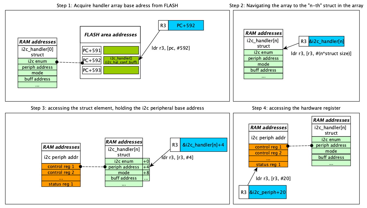
ldr r3, [pc, #592]loads a word from the literal pool at(PC+4)+592, which contains the address ofi2c_hal_conf_buff(the pointer variable itself pointing to thei2c_handlerarray), having address0x200000d8i2c_handlerarray, which isi2c_hal_conf_buffpointer value. This match was done previously during pointer initializations in code not shown here.ldr r3, [r3, #0]loads the value ofi2c_hal_conf_buffat offset 0 (dereferencing the pointer variable, accessing the element). R3 now contains the address of the i2c_handler array at the array n-th element. Note: being the first element of the array, it corresponds to the base address of thei2c_hal_conf_buffand so this step could have been optimized away.ldr r3, [r3, #4]loads the.periphfield fromi2c_handler[n-th] (.periph is offset 4 bytes from the struct base). This field contains the I2C peripheral base address, which is stored in R3.ldr r3, [r3, #20]loads the SR1 register content using the I2C peripheral base address in R3 plus offset 20 (which is the SR1 register offset). R3 now contains the actual SR1 value.
Now, after a chain of 4 commands, R3 contains the value of an hardware I2C register starting from an address of an array of struct. Since the value of the register is stored inside the stack in a local variable, the instruction str r3, [r7, #12] saves this value to the stack at R7+12, storing it in the local variable sr1_buff. As we know now, this will be referred in the code as R7+12, no explicit sr1_buff reference can be found, being local.
Identifying memory overlaps
In this scenario, we need to chase what’s inside at the address memory of the buff[] to understand what was sent. This will be useful later on during the exploit. In the i2c_test the (non-static) buff[] was at SP+20 = 0x20004FC4. Let’s identify a possible overlap by checking what’s inside at the RAM location 0x20004FC4 when inside the i2c_hal_i2c1_isr(). To do that, when running the command “info registers” inside the interrupt function we can identify what we computed the SP to be 0x20004FA8, here the output:
info registers @i2c_hal_i2c1_isr()
[...]
r7             0x20004fa8
[...]
sp             0x20004fa8
lr             0x800290b
pc             0x800154c   <i2c_hal_i2c1_isr+36>
[...]
In this scenario, as identified already from the assembly of the ISR, the stack pointer corresponds to R7, so makes sense to see it equal to SP = 0x20004fa8. Also, in this ISR we saw that the stack size is 32 bytes, so the beginning of the stack is 0x20004fa8 + 32 = 0x20004fc8. The buff[] in i2c_test was located at 0x20004FC4, which is within the new stack frame, 28 bytes from the end. This means that the pointer of the buffer, now that we are inside the ISR, will correspond to data in the stack of the ISR itself. Therefore, the question is what is present at the 28th byte above to the SP? This can be easily understood with a diagram:
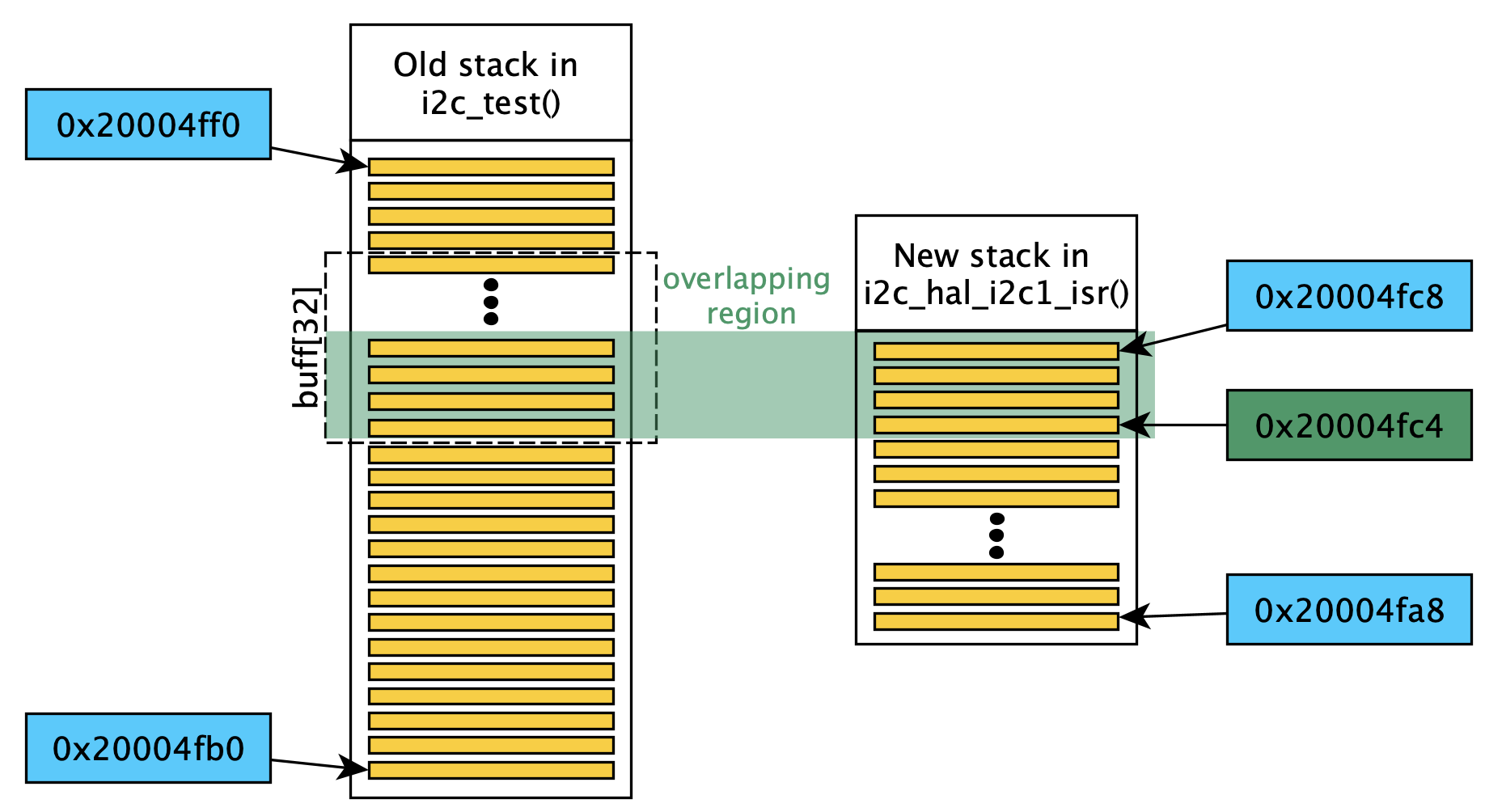
The answer is in the assembly: after allocating the 32 bytes in the ISR, the SP = 0x20004FA8. Therefore, 32bytes above, the stack will begin at SP-32 = 0x20004FC8. And with the prologue instructions at the entrance of 12 bytes being push {r4, r7, lr}, at 0x20004FC4 there’s the LSB of the 4 bytes LR register, LR = 0x8000290B. This value corresponds to the value addressed by the first element of the buff[]!
And that is exactly what we are sending through I2C! This has couple of consequences: either disastrous real world interactions, or subtle data corruption, or even allowing to maliciously read the memory of your embedded system in certain scenarios. To demonstrate an example of the real world interaction, let’s instrument some code to analyse how we can, for example, blink an LED just by writing a random data in a completely naive manner.
The “exploit”, blinking an LED through undefined behaviors
Now is possible to recreate the situation in a controlled environment by putting together all of what was learnt so far. What would happens if we don’t initialize a variable that we read? It will contain “garbage” and any action to it it will be an undefined behavior. But now we know that garbage is not “random”, and undefined is not unknown.
For example, let’s consider a pointer storage in a variable:
attribute((noinline)) uint32_t* gpio_corrupt(void){ volatile uint32_t *reg = 0; // reg is declared as a 32bit pointer, nullptr initialized reg = (uint32_t *)(&(GPIO_HAL_PORTC->ODR)); // store pointer of ODR in reg return reg;}
It is declared as noinline to be sure it is compiled as a function call, and therefore, forcing it to work in a given stack reference different from the code outside the gpio_corrupt() itself and generating push/pop instructions. Here a microcontroller’s GPIO control register address is stored in reg, like in a scenario where it can be used as a handler. And then, we immediately exit with a return reg.
Afterwards, we call immediately gpio_corrupt_test(), which uses the content of uninitialized reg_test as address. This is a possible scenario, but “undefined behavior” happens when initializations are missing:
__attribute__((noinline)) uint32_t* gpio_corrupt_test(void){ volatile uint32_t reg_test; // reg_test, used as a pointer later, is not initialized - what can happen? *(volatile uint32_t*)reg_test = 0; // write 0 to the location pointed by reg return (volatile uint32_t*)reg_test;}
Now, we know what undefined behavior means. It is, in this simple case, an untracked stack manipulations. More precisely, in the gpio_corrupt() function the assembly is:
attribute((noinline)) uint32_t* gpio_corrupt(void){80027b4: b480 push {r7}80027b6: b083 sub sp, #1280027b8: af00 add r7, sp, #080027ba: 2300 movs r3, #080027bc: 607b str r3, [r7, #4][...]80027c6: 370c adds r7, #1280027c8: 46bd mov sp, r780027ca: bc80 pop {r7}80027cc: 4770 bx lr
A 12 byte stack is allocated and the memory manipulations are then made, before returning back by counting backwards in the stack by 12, effectively deallocating it and making it available for use by other functions. Here the actual variable reg is initialized via R3 as buffer register using movs r3, #0. And then is stored at R7+4 via the str r3, [r7, #4].
This second function, the gpio_corrupt_test() has this assembly:
attribute((noinline)) uint32_t* gpio_corrupt_test(void){80027d4: b480 push {r7}80027d6: b083 sub sp, #1280027d8: af00 add r7, sp, #080027da: 687b ldr r3, [r7, #4][...]80027e6: 370c adds r7, #1280027e8: 46bd mov sp, r780027ea: bc80 pop {r7}80027ec: 4770 bx lr
The prologue and epilogue, listed above for both functions, are exactly the same. Note that instructions’ addresses are 32 bytes apart in FLASH between those two functions.
In the gpio_corrupt_test() assembly, there’s a ldr r3, [r7, #4] preceeded by nothing, but also here reg_test is R7+4. It means that, since R7 = SP as before with no other events happening in between, it will read exactly the same SP content that was in the previous function. In this case SP was containing garbage, writing to it will result in “undefined behavior”. But here that represented the content of the previous function that contained the SFR register reference.
And now, if I write a value at the uninitialized address of reg_test, here’s what happens, as shown in this GIF animation:
I’m turnin on an LED by writing to an uninitialized data address of a local variable. This means in reality, in real world scenario, it can be anything. And in the world of firmware, it can have enormous physical consequences!
Takeaway
This article shows what a single missing keyword can really hide. I traced a practical example through the layers: from C’s theoretical rules about variable lifetime, down to stack frame manipulation and investigation through the CPU registers, ultimately demonstrating “undefined behavior” by exploiting it to blink an LED.
The investigation required exploring static vs automatic variables, stack allocation mechanics, ARM Thumb assembly, and how “garbage” data is actually deterministic leftover state.
So next time you see something strange in your embedded system you’ll appreciate how fascinating a bug can be when it becomes a butterfly (effect). 🦋
