
Maybe some of you knows well the so called GertDuino, an expansion board of the RaspberryPi. It is like an Arduino which can communicate with the Rasp, and moreover it also mount an Atmega48 which can be used to emulate an RTC. Yes, I’m going to talk about this.
The challenge: proof-of-concept of commercial real time clocks emulation (DS1307).
I saw my board with a PIC18 microcontroller, that embeds an RTC module inside the microcontroller. Since I’ve recently tried the on-chip RTC capabilities of my PIC, the idea is born spontaneously: can I cheat my Pi by making it see a fake (but working) DS1307 RTC? Well, if I’m writing this, means that the answer is yes. And this, of course, can be applied to any single board computer (like Raspberry) which carry an I2C interface. This can be helpful even if you have a different microcontroller, because the software libraries can (in an ugly way) be portable! Oh, and the microcontroller which emulates the DS runs at 3V3 and it is even 5V tolerant, so no need of any adapter, when working with RaspberryPi.
The RTC nostalgia
 Dallas Semiconductor were quite known as a company which design and manufacture mixed-signal semicoductors and a lot of digital and analog complete amazing modules (like voltage references, battery handlung, real time clocks ecc). With our hands we can touch the old real time clocks inside old computers, like the firsts IBM in the Intel 80286 epoch. A lot of sweet memories with my old and still working IBM PS/2, with the (now battery drained) DS1287 (photo on the left).
Now the company has been acquired from the Maxim Semiconductor, which still produce some of their products. The RTC series still exist and will continue, as long as the driver support from embedded Linux distributions, and are currently still used in a lot of microcontroller based projects and commercial products. The firsts embedded RTCs have their own battery embedded in the package, which is called E-DIP package. They was huge and if the battery wears out, you can forget to disconnect the supply, or change the chip, or… breaking it and apply an external battery!
Apparently, a famous RTC used, especially in hobbysts and makers is the DS1307. A very basic RTC, without any alarm system capabilities. For that reason, since my microcontroller with RTC module is supporting alarm clocks too, I may need, in the future, to change and emulate a different RTC, like an DS1337. Ah, today are packed in standard DIP or small SO packages without the internal battery, but I’ve found that are still exist the E-DIP packages. Interesting.
The DS1307 works with a logical registers interface. Physically the access is made through 3 wires using the I2C bus, where the RTC is always a slave (SCL, SDA, GND). Except for the first byte on the bus, which identify the slave (here this DS has always a 0x68 bus address) plus a read/write bit mode, the real data, which can be named as payload, can be sent in writing (to DS) or retrieved in reading (from DS) mode. Refer to datasheet for details. The trick is simply to emulate the behaviour and timings. If you know it, you can become it. 😀
Firmware and code portability
When I started writing the code for testing an EEPROM, since the need of very standard interface like the I2C, I thought to use the already written libraries from the XC8 compiler: but I found their names and usage too less intuitive and with the same time spent in learning how to use them I could write my own. So as a good exercise I wrote them and now, for this project, are also improved a bit, using a lot of defines and enumerations, allowing to increase the functionalities and simplifying their usage and writing, and keeping them quite inexpensive in terms of allocated resources. The tool used are:
- MPLAB X IDE, with the XC8 compiler (free version)
- PIC18F47J53, mounted on this italian development board, known as PIERIN Pic18.
- 32768Hz quartz, disassembled from a thermostat or so, I didn’t remember
- RaspberryPi for tests
- GitHub
- Coffee
I’ve also though that if a new microcontroller needs to be changed, the code should be portable, or at least should not be painful when porting it. So I thought to a very primitive level of abstraction layers, written in pure C. The whole code is here on GitHub.
Abstraction Layers
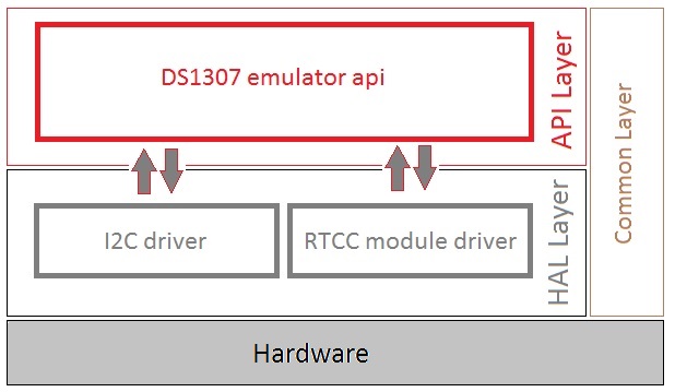
The firmware is composed by three logical structures, but keep in mind that I’m talking about firmware, so are not quite imponent and distant these layers between each other, as in common PC applications:
- The classic main and other configuration files, like interrupt, config bits ecc, that are common to other functions, not only to the DS emulation in case other tasks are implemented. Let’s call them as common layer, because is common to the other layers, it is a “vertical” layer.
- The implementation of the higher level of the DS algorithm, that contains procedures which are calling the hardware drivers in a proper order. Name it as api layer (a very basic form of application programming interface). More functions at this level means more things done by the MCU. Here can be managed the hardware allocation for each task.
- The drivers called and used by the previous layer, in which are present the procedures that are implementation dependent (the hardware handling). Changing the hardware means change (or add) some row in these files. So they are a basic form of hal layer (hardware abstraction layer interface).
Each of them are interacting with each other, roughly, in this way:
Thanks to the API layer, I can improve the emulator with more features and other hardware support, due to practical experimentation purposes, leading to a more enriched, open project. For sure I will need to implement a software RTC feature for platforms that don’t have that module. Last but not least, the “compass” of the emulator was this table, which is the register interface of the DS1307, one eye on the code and the other on this table:

The various defines in the code in the HAL and API layers are related to this table. Those definitions are not well compartmentalized from one layer to another, because I thought to be more flexible w.r.t. emulator platform rather than the emulated object itself. Nevertheless, a new emulated object will bring to a complete review of the layers, because different APIs are needed as much as a different hadware (the HAL) behavior as different are the required procedures of the driver.
Hardware setup and demo tests
Now it’s time to test if everything works. I started directly on the RaspberryPi using the hwclock routines from terminal and its embedded I2C module. Strange things happened, from writing an year and reading another to get the Pi freaking out due to detected error configurations on the DS. So more simple functions were needed to test it, in a very fast way. Here my old school Arduino Duemilanove became very useful, by using and adapting some DS1307 libraries, to run a complete test of basic interactions, check the change of settings and play with the NVRAM.
Coherence and settings tests
Few main bugs in my code are find by using some Arduino libraries. But I used them to see the first heart beat. The Adafruit RTClib, where some of them are modified to fit my first alive tests. Then a code from a guy on Instructables, I’ve just googled for a testing function. Taken the I2C pins A4 for the SDA and A5 for the SCK from the Arduino, and connecting them to my Pierin, I finally make the PIC18 seen by the Arduino. But it was frozen. Of course, I forgot the little brother, the timekeeping crystal on RC0 and RC1 oscillator pins.

And then, it started breathing:
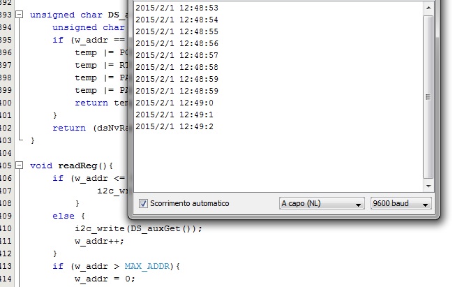
The doctor said – time of birth: 12pm, 48′ and 53″. The date was taken using the RTC.adjust(DateTime(__DATE__, __TIME__)); call. Moreover, I can easily test the output pin functionalities, halting the clock, change output settings and testing the NVRAM by using the RTClib. At this stage, the difference with the original DS1307, is the frequency at the output of RTC pin. It is not a bug, but the PIC hardware support only 2 modes instead of 4. If needed, can be done easily in software, but now, as stated in the first title, I’m at a proof-of-concept phase. Below there is the output pin table of DS1307 with shaded modes that are not currently available in this emulated module:

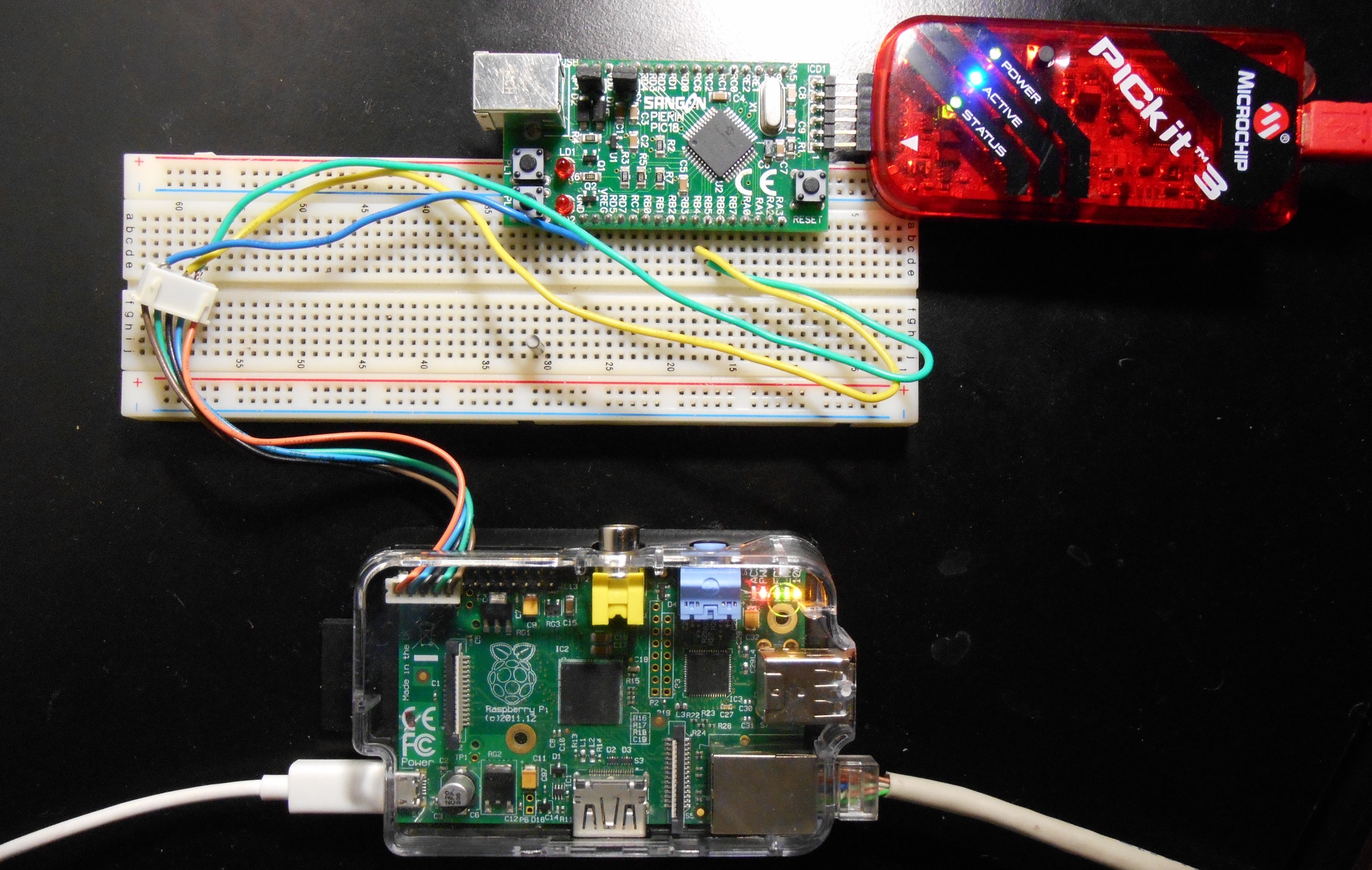
RaspberryPi: connection and setup
The systems which will use this emulator would be also any computer with an I2C port. Here, a Raspberry Pi is very appropriate. I’ve the RPi B rev.2, so I’ve used the I2C module 1, using pins 2 and 3 (plus GND and 3V3) of the R2 reference. Connections are made by taking care, in testing phase with PIC18 powered by my PC, to have the ground in common with all systems and then connecting the SCL1 and SDA1 ports of the PIC to the respectively GPIO2 and 3 of the Pi: 
Now it is needed the software setup under Linux (here Raspbian). One can follow the standard steps for the DS1307 written everywhere, but sometimes bad things happens. Here my final setup (I would to thanks the source http://en.gnublin.org/index.php/RTC_DS1307).
-
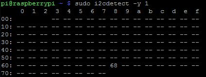
- Firstly check if the RTC bus is alive, by typing sudo i2cdetect -y 1:
- Then enter in bash mode by typing sudo bash and only then type echo ds1307 0x68 > /sys/bus/i2c/devices/i2c-1/new_device to put on the i2c bus 1 a new device called ds1307 at address 0x68. This data is being used by the Hwclock procedures. If an error arise try to remove something, like echo 0x68 > /sys/bus/i2c/devices/i2c-1/delete_device and repeat the new device insertion.
- Load the already present (it should be) module “ds1307” to the kernel using (I did it in bash mode but it is not a mandatory) modprobe rtc_ds1307 2>/dev/null 1>&2. The numbers are meaning that the standard error (2) is trashed and write the output (1) also in in stadard error. This allow the hwclock utility to avoid problem related to “IOCTL” not working calls in which you can step into, and it is used to keep trace of the output of commands without printing them on the screen.
- ONLY IF YOU GET ERRORS WITH HWCLOCK: To avoid further problems, which are not taken into accout by the standard guides, it is needed to add the physical rtc device, which often is not present, allowing problems of ioctl type. I’ve added to rtc0 by typing: mknod /dev/rtc0 c 253 0 2>/dev/null 1>&2.
- Check with dmesg that is something positive like this:
[ 5061.101787] rtc-ds1307 1-0068: rtc core: registered ds1307 as rtc0
[ 5061.101837] rtc-ds1307 1-0068: 56 bytes nvram
[ 5061.101895] i2c i2c-1: new_device: Instantiated device ds1307 at 0x68
- For verification purposes, typing lsmod should output the rtc_ds1307 module somwehere.
- Firstly check if the RTC bus is alive, by typing sudo i2cdetect -y 1:
Now exit from bash, and if you want you can setup a script from the linked Gnublin source. I didn’t test it. Now, if you need to test the device using the i2c utilities, you need to delete the device (step 2) to free the bus address reservation. There is not much to show on photos, but I put my test bench just to make this article a bit more coloured. 🙂
And the tick is got.

Unix epoch and misunderstandings
A curious thing is related to the date previous to year 2000. If I have the 1970 as starting date (the first year of the Unix epoch), issuing the hwclock -w will write this date to the RTC. But any read was wrong, giving back the year 2066. Writing manually the registers produces a normal results, so the only conclusion, since these RTC are supporting dates from years 00 (2000) to 99 (2099), the hwclock is making something that is misunderstood since will work on more than 8bit to represent that value, but the RTC understand this as a 2066 due to some millennim transformation. In fact, with date from 2000 to 2038 everithing is fine and surprisingly everything it is not my fault. But why 2038? Don’t get me wrong, the RTC module can handle dates to 2099 correctly, but any Unix derived OS can not. In fact, I’ve sperimented that dates (dd/mm/aaaa format) until the 19/01/2038 03.14.08 am are correct. But the second later the end of the Unix epoch, any read will indroduce a mismatch error. And any set over this date is notified to be… correctly wrong. All this is because the timebase variable which keep tracks of the total seconds from the 01/01/1970 12.00.00 midnight, is a 32bit signed and will wrap at that date in 2038. That will be the thirtyennium bug or whatever, but I doubt that the world will collapse in a black hole. Here, is what an end of epoch will appear:
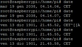
If you wake up in the morning, without smog, smarthphones, computers and in the street you see only stagecoaches and horses with gentleman or a huge poverty, well, probably you have travelled in time. In the meantime, the others will see on their PC/smartphone/ecc clocks this awkward date. There are many proposed solutions, but it is not a trivial thing.
Future improvements and lessons learned
During this trip I’ve discovered how powerful can be an on-chip module, how much can be simplified the programmer’s life and firmware execution. Since I’m an electronic engineer at heart, I’ve made some progress in the coding art, despite it still look not so perfect. And with the excuse of debugging the I2C bus, I’ve finally bought the PicKit 3 and my life became easy and free from bootloaders or fuse registers unchangeable.
As soon as I can I’ll try to implement the alarm part, which can be used to trigger stuff on the GPIOs of the RPi. In this way I may need to became compatible with another version of Dallas Semiconductor real-time clock.
And now, getting involved in bus protocols and by discovering how powerful can be just an 8-bit microcontroller, how is difficult to fill even 5KB of flash and with the help of past experieces, new ideas are under development. As an engineering mind is in constant motion.
On the background of this article, follows DS1307 RTC for Arduino here.

Many hobbyst now use DS3231 because is cheap and much more precise than a DS1307 because it has the crystal inside. Most cheap DS1307 have bad crystal, I got a module that is 30 seconds ahead every day!
LikeLike
Good to know! Regarding the DS1307 precision, if you have a bad timekeeping accuracy, it is only fault of the external crystal and may also be incompatible with the integrated load capacitors in the IC. Moreover, if you buy the “china” modules, they are not only containing (probably) bad parts, but also the general schematic used that you find on eBay is dangerous, because is putting current to the non-rechargeable lithium cell when powered from 5V. This requires some mods if using it on the long term, where actually the accuracy matters.
LikeLike
Yes, usually if you have a bad DS1307 module the fault is on the external crystal. But since the DS3231 is cheap too, it’s much better to use this than the DS1307, the crystal inside the chip has thermal compensation too.
The DS3231 has the battery fault charging circuit too.
LikeLike
Yes, indeed. The concept in this article is just to try to emulate the whole chip by having just the main MCU with its crystal. Basically a software package that is being compatible with an existing interface, even just for experimenting and prototyping purposes. When I have time, I for sure upgrade it to support also the DS3231 protocol and, why not, also others that may be useful.
LikeLike