
In the last PWM discussion, we devised how is composed the average current, specially when the PWM frequency is faster than it should be, making the period duration comparable with the rise and fall slopes duration of the current. The results were packed up in 2 equations to summarize what is the best choice for the PWM period. This was expressed with the maximum frequency (eq. 33 from the last article) and the minimum (eq. 34), namely:


From which, developing the time duration of the minimum on-time and off-time, given the system architecture, is possible to find a practical value of the period.
How much slow the PWM signal can be?
In many cases, the PWM frequency has also a lower limit which depends on the application. If human eye is involved, there is the flicker fusion threshold involved. This has been noted being not lower than 50 Hz; even though we are very edgy here. But during saccades (saccadic eye movement, or moving our sight from one point to another), frequencies up to 2 or 3 kHz can be easily detected.
In fact, by moving the eye durin a saccadic movement, which happens relatively fast, the light will continuously hit a different part of the retina, behaving exactly like an oscilloscope, excuse me the analogy. Or, like a camera which is moved during a shot. A picture of what you would see during a saccadic while staring initially to a LED light with some random blinking, is shown here in Figure 1.

A scope acquisition of the same signal is shown here:
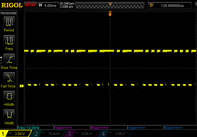
Now is more clear what I mean when the eye is acting as a scope. I presume this delay in our eyes is to give time to the brain to get the image better at the subconsciuous level. But I leave this to the experts.
As a result, also the lower limit depends on the application. If no blink artifact (like in Figure 1) shall be visible at any condition, more than 3kHz is a good starting point. Otherwise, 60 or maybe 100 Hz is good enough, making the design of the PWM less troublemaker under the EMC point of view.
Architecting the digital part: how many bits?
After all the considerations so far, it is possible to finally drive the LED! But sometimes (i.e. always in the real world) is required a certain minimum resolution. This translated in the requirements of how many bits are required when generating the PWM signal.
With a generic n-bit PWM, the available steps are 


First, since a duty cycle of 100% means an always-on signal, thus is only DC in the spectrum, the minimum value below 100% shall comply with the 

Just to recap, the 

while the 

Since the maximum duty cycle is 


To comply with the first requirement to properly deal with the analog capabilities of the driver, the minium on-time shall be as long as at least the time duration of a single bit in the PWM word:

This automatically bind to the Dimming Ratio requirement, as briefly mentioned the Part 1/3. It was found that the Dimming Ratio is:

which translates from (6) into:

The (eq. 8) shall be compared with the analog counter part. This means that to find the minimum required number of bits, the (eq. 6) shall be reversed for 

Yes, the sign 
Few more words on the suggetsed maximum number of bits
If proper precision is required to all the PWM steps, the (eq. 7) apply only at the first and the last PWM step. Which mean that once the current reached the right value, an “infinitesimal” step increase can be applied (i.e. with infinine number of bit of PWM word, giving no quantization error). So while in the middle of the dynamics, a more resolution can be deployed; but for sake of simplicity, almost everywhere is used a fixed PWM resolution.
What is important is to get to know the error introduced by the digital control: the simple way here is to take into account the equivalent DC output from the PWM, and how does it drift from an ideal infinite resolution PWM system.
First, the precision here is mainly related to the analog front-end of the driver. It is known that there are ramps of finite amount of time, greater than 0, of duration from eq. 4 and 5, namely
The Eq. 7 shows what is the number of bits to be used in the PWM controller to “hide” those analog errors (i.e. the ramps). If we call the number found in the Eq. 7 

Lowering


the relative error is given by the ratio of Eq. 8a with the ideal average current:

Regarding the resolution, if the ramps are necessary to reach their steady state and the delay of the real analog driver is considered, then the number of bits 

