
Recently I found that today almost lighbulbs are made with power LEDs. And surprisingly most of them are made so cheap that the controller fails far away before its lifetime. At least for what I’ve experienced with few models. Most of them seems to work well, and I think that LEDs are the future for many more things, more than we imagine nowadays.
This triggered in me the need to start experimenting how difficult is driving with consciousness a power LED system, containing mainly the driver and the LED itself, of course.
Lighting up an LED: what does it means?
Lighting up an LED is simple. Put a resistor in series to achieve a correct current with respect to the supply and the forward voltage of the LED, and voilà, it is light. You can realize that if dimensioning badly these parameters, the LED become hot, leading to change also its colour. Becaming hot, will lower its forward voltage and then more current will flow. As you may realize, this is not ideal when color precision, high power and energy savings are the keyword of a design. An indicator LED (few mW of light) can be designed with a constant voltage, and due to the low energy absorbed, there is an absolute low wasted energy. But relatively speaking, the energy loss is very high.
Let’s consider the circuit below:

The wasted power is always the difference of the voltages between the LED and the supply. So we have that 


For now a switching regulator is part of the next steps, if making a linear regulator will be successful.
Constant current linear regulator
The most simple linear regulator is made by two transistors. Through the 2.2K resistor is powered the T2, which turn on the LED. The drop on R is senses by T1 which choke the base of T2 on order to keep the current on T2 around to 
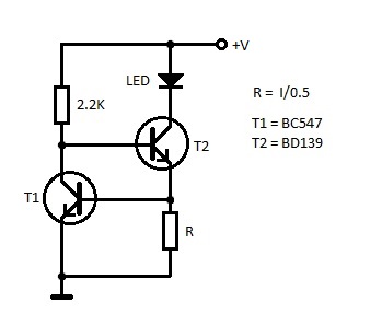
This is fine if one does NOT need high stability over voltage range, considering also that the Vbe are almost the same, therefore given a current required, the resistor cannot be reduced to reduce wasted power. Since T1 is driven in its active region, the stability corresponds to its plot of the collector’s current VS the collector-emitter voltage:
A possible and more controllable solution is using the LM78xx in constant current source configuration. The issue is the limited linearity in current, and moreover we cannot change the reference voltage without making strange things, leading to waste a lot more power in sensing the current (dropout cannot be lower that 1.25V in these regulators).
Therefore I have ended up with an initial trial in these drivers by making something more “controlled”.
Linear constant current: the challenge
I need to make something very precise, simple and instructive for myself. I found the classic configuration of a linear current regulator, but using an Operational Amplifier, a MOSFET and shunt resistor. Here is the principle of what I am talking about:

Assuming a sufficient supply for the OpAmp, V1 must be high enough to allow current flowing in Rs so that the current can follow the rule 
- V1 must be equal or greater than the forward voltage of D1 plus the voltage drop on Rs and the Vds in linearity of the MOSFET, in worst condition (MOSFET works in saturation region if higher voltage is applied, enabling the analog control of the light, but also higher wasted power).
- The voltage drop on Rs must be the voltage on CLK1 pin
The #2 condition is the key of this circuit, and it is the OpAmp purpose. The values and components in the figure are just for reference. The sense resistor substantially determine the minimum voltage applied to the LED: if the resistor need to drop 3.3V, these must be the starting point for the minimum voltage. We are designing a linear current regulator with a “dropout” of 3.3V! It is quite a lot of wasted power: 
But here the advantage: I can change the reference in order to reduce the wasted power! And its linearity is order of magnitude higher that the configurations shown above (yes, with the expense to use an op-amp). In the reality I need to slow down my circuit response, because low sense resistor will lead to instability.
The real world: demo boards
I then build a demo board to test the thermal calculus applied on power components (LEDs, MOSFET, Sense Resistors), without any concerns about efficiency: one need first to understand if the main concept works, with the simplest conditions… the roots of the tree! 🙂 To add a bit of fun, I will try to design a setup of 4 LEDs, Red, Green, Blue and White.
Which is the accuracy of the design? The precision is dependant from the op-amp’s offset: a sensed voltage of 3.3V with 9mV offset, bring uncertainty of few hundredths of percent. Then the other main source of error is the sense resistor. Here I used 5% power resistors, so the main error in current stand point can be said to be 5%.
Thermal experiments
I choose the Luxeon Rebel series LEDs, which provides also a public well designed thermal pad for normal 2-layer PCBs. Following the basic rules of thermal design (I should write something about that in the future), I have interfaced an heatsink to a pad, which brings a thermal resistance of 7 °C/W, junction to heatsink, which is from the LED to the top PCB anding to the bottom layer:

The design takes in consideration the maximum forward voltage of the LED, and its maximum current. In this design, 4 LEDs are used (Red, Green, Blue, White) and only white have the higher voltage and so the higher power, so the dimensioning is made on the white to achieve the worst case.
A bit of math
The maximum junction temperature allowed is 150°C, reduced to 130°C for reliability. The white LED dissipates up to 2.2W at 700mA. Thermal resistance of the junction to case of LED is 10°C/W for these LEDs. So:
![[\Theta_{junction-case} + \Theta_{case-heatsink} + \Theta_{heatsink-ambient}]\cdot P_{LED} = T_j - T_{ambient}](https://s0.wp.com/latex.php?latex=%5B%5CTheta_%7Bjunction-case%7D+%2B+%5CTheta_%7Bcase-heatsink%7D+%2B+%5CTheta_%7Bheatsink-ambient%7D%5D%5Ccdot+P_%7BLED%7D+%3D+T_j+-+T_%7Bambient%7D&bg=ffffff&fg=424242&s=0&c=20201002)
Thanks to the thermal pads, the heat is trasferred to the bottom and from that towards to ambient, using an heatsink. Where Tambient is 40°C, in order to consider the maximum allowed one. Calculus lead to use a 24 °C/W, the used one is 25°C/W, can be unsafe for the LED to work at 40°C, but it is well cooled at 25°C. To stay even more safe in a reasonable way, the power of the LED is assumed to be entirely transformed in heat, while actually only around 60% is wasted, due to efficacy the LED to be around 40% and therefore that quantity of light is transformed in light, and this percentage will vary from one color to another. With this assumption and these LEDs, I can use them at 40°C too with a smaller heatsink.
The remaining power due to overvoltages is absorbed by the MOSFET.Again, Tj will be 130°C. Here, if I decide to power my board with maximum 9V, the drop on the MOSFET will be:

And using the (1) only with the junction-to-case resistance, with parameters extracted from the datasheet of the BUZ70 used:

The system will work up to 40°C of ambient temperature, still air. The same happens for the power MOSFET, which is dimensioned to dissipate up to a supply voltage of 9V (my maximum supply allowed) minus the minimum forward voltage between the 4 LEDs, leading to a worst case condition and so higher power dissipated on MOSFET corresponding to lower power dissipated on LED, here is the Red one, which have the lower voltage drop. The MOSFET uses then a simple TO-220 heatsink of 21°C/W. Calculus lead to Θca = 32°C/W, but I had only these larger one at the moment of the test.
Since it is just a proof of concept, the sense resistor drops a very high reference voltage, here 3.3V. Which at 700mA of maximum current, dissipates up to 2.5W. A small vitreous enamelled wirewound power resistor is used.
The PCB design
You can see the schematic of the final system, with different supply rails for op-amp and LEDs, which can be also merged togheter. To feel safe, I’ve added some pulldown resistors, keeping the LEDs off if no signal is applied.

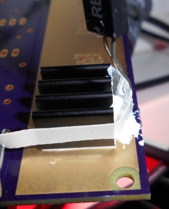
The placement takes into account the dimensions of the heatsink, shown here:

The Luxeon Rebel LED pad used brings the heat down to bottom PCB with 7°C/W of thermal resistance. But how to place the heatsink? I choose a PLCC heatsink and glued to the bottom with a thermal tape. Of course, the bottom must no contain the soldermask, freeing the condutors.
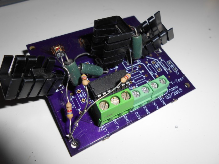
Here the demo board ordered exclusively from OSH Park:
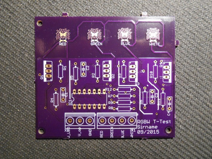
Nice work, even the tiny 0.25mm vias of thermal pads are made correctly! And here you can see the bottom section with the exposed conductor in which will be mounted the heatsink on it. Note that this solution is adopted since it is a regular FR4 and not an aluminum PCB:

Since I am an evil genius which tries to drive 4 LEDs, I bought 3 heatsinks both for LEDs and MOSFETs. For that reason I will show pictures of only white and separately the RGB test.
First tests
To see the regulation, I probed the signal on the sense resistor. In the real world, this is how my regulator regulates, when applying a 50% duty cycle:

This beacuse we drive a capacitive load (i.e. the MOSFET gate!), introducing a pole which depends also on the output resistance of the op-amp, reducing the phase margin too much. I have found that my circuit is one of the most unstable systems. By improving the reliability inserting a resistance between opamp and MOSFET’s gate, the oscillation will increases. Such a pain in the amp.
The answer to this problem is to increase the phase margin of the system, and I chose to use a Lead Compensation circuitry, this will reduce the bandwidth of the system to a known value, in my case to around 160 kHz, choosing a values of R and C of 100Ω and 10nF, after a bit of math and trials, not depending anymore from the operational amplifier’s bandwidth. This compensation seems to work, also on various supply ranges, because reducing the Vds will increase the capacitance Ciss, so testing over various suply voltages worth something. Here the smoothed output:

Still, I did not made any rising time tests, but I will need to. This linear regulator can modulate signals up to 160kHz! Any switching LED regulator do not handle modulating frequencies up to few tens of kHz. Is this useful? It depends: we will see in the next episodes. “Is it more efficient than a linear COTS component?” “No.” “Can be improved to be more efficient?” “Yes.” “When?” “Later.” “How w…” “shut up”.
The thermal pad of LED becomes quite hot, demonstrating that some heat is tranferred. I run the LED for a while, with no damage, I need only to test it in an environment of around 40°C, since this is the temperature at which needs to survive by design. Just for curiosity, I probed the temperature, to make a quantification of the “finger test”, by putting an NTC (did you know how to use it?) as close as possible to the heatsink, fixing the probe with a thermal grease:
What is a finger test? When you put your finger on a surface and you can’t stant the finger, it is usually more than 60°C. And here the system set-up to use 3 LEDs:

Color power
The white works, I did not made a serious comparison with other light sources, but is visible like almost as a 5W or 6W neon bulb at first approximation. The picture is taken with a partially hidden LED behind the MOSFET heatsink otherwise the camera will close completely the shutter.

I then discovered that the offset is sufficient to light up dimly the LEDs when they are supposed to be fully off (here you can spot the blue one behind the resistor). Injecting current in sense reistors, to compensate the offset voltage will solve the problem. Must be applied a resistor in order to flow a current at least equal to the current generated by the offset, here 
Let the light begins! The 5V-3.3V voltage shift is provided through a blob of air soldered resistors placed in the inputs:


The red trial:

The LEDs were soldered using an hot air gun, heating from the bottom: the pad is used then as a heating tranferrer for the soldering phase. The Luxeon Rebel LEDs are demonstrated to be strenght enough.
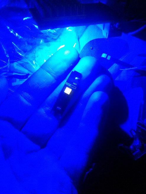
The blue will shows an interesting thing: exposes the fluorescent materials!

With an another set of blue LED (here more blue, to be precise I’ve used a Royal Blue when I taken the picture below) I discovered that my small toolbox is somehow fluorescent (the light green one). In the center of the picture, you can see another board disconnected in which the white led seems to emits on its own, while it is just converting back the royal blue to a more sensible and wide wavelenght range, i.e. white, thanks to its covering resin made of fluorescent material.

Another LED from a smartphone flash, that re-emits under the Royal Blue:
Little demo
In the video posted here, can be appreciated the variety of shades that can be represented. With a firmware handling 8bits per colour, here can be represented 255 times 255 times 255 colours, i.e. 16,581,375 color shades. Implementing the white, an even more precise white light can be generated (did you mentioned Philips Hue?). For the future improvements, I will release also the code and stuff.
Future improvements
The next version will have the offset compensation, better LED positioning, higher efficiency. The concept works, but now a proper firmware will be developed, strarting from implementing a better script in Python which communicates with the Arduino and selects the colour.
Maybe for efficiency reasons and since I don’t need speed, I will “switch to switching” for future versions. For now, I am satisfied of having touched with hands the “inefficiency” of the linear current sources for LEDs, which is the price to pay if you want precision and, eventually, high bandwidth.

3 thoughts on “Current sources for LEDs: firsts DIY impressions”