

In the watchmaking industry there are not only cogs and gears. Nowadays, even the high watchmaking industry focuses on sophisticated digital technology, to combine it with the fine art of mechanics.
And it exists, once open-source, even an RTOS owned by Swatch, for which I had the pleasure to use, and mostly to be mentored by the main designer and open source enthusiast behind that.
It was an afternoon conversation about what an old microcontroller can do, and that small batch of PIC12 parts on the corner of the desk were spotted, discarded as a commodity just to interface buttons and the like. And I was given a bunch of them to play by him. Just to not throw them away like that.
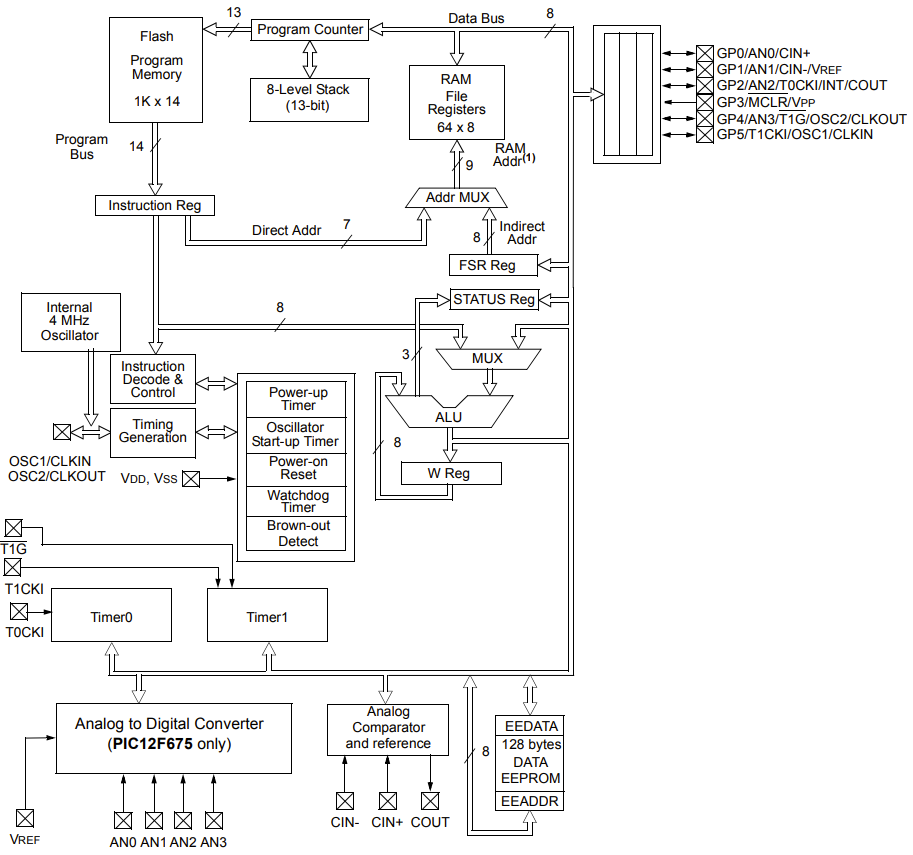
The part given is the Microchip PIC12F629, a “monster” with the usual exoteric Microchip format style, 1024 words of flash and 64 bytes of RAM. And by words means 14-bit wide word, for an effective 1792 bytes of flash.

The structure is very simple and primitive, with the CPU still visible in all its parts (ALU, PC, IR, Decoder ecc), which I love to see in this way. And the 14-bit esoteric is just because is all so simple that the user has direct awareness of the op-code data width, which does not use any translator, and the FLASH memory configuration is adapted to the 14-bit op-code:
So we have:
- 2x timers
- 6 GPIOs
- Support for crystal
- 1024 14-bit words
- 64 bytes of RAM
- …enough!
Before finishing the list, I realize I have already more than enough resources. And inspiration was just missing.
I started to wonder if the project can be able to deal with (extremely basic) 2D graphics and text animation. But after remembering that was given by who works in the watchmaking field, why not making an RTC with an animated display and user interface? Here it was born, from the name of the person behind this RTOS, who does not share the enthusiasm for PIC parts, to poke him, EdoSplay was born.
The development started with a proof of concept of the core elements described later on, like communications, animation algorithms, and so on. The very basic was tested out on a breadboard, successfully.

This means that the Proof of Concept against myself worked, and it was time to start thinking about the project a bit more thoroughly.
The system design
Since we must stay short in code, should be used as much hardware as possible. Also, it shall be a real real-time clock, so care should be placed at the time precision. And there is no point to design all the supporting electronics for this project, so only the indispensable parts will be customized, the rest will be bought off the shelf. But all of the firmware has to be self made, since nothing was available for such a small memories footprint.
Then a display is needed, the most easy to use with a simple SPI, is the MAX7219, that requires at least 4V. So to keep it simple, a single 5V system should be used. The SPI can be easily bit banged – putting some pressure on the code space, but the PIC12 has no communication systems at all, and SPI is the simplest to implement. Such a display is easily available already with the MAX IC controller.
Since would be nice to have the EdoSplay portable, a battery is needed. Now, multiple cells in series and a LDO would work, bus since a more efficient DC-DC that can boost to 5V from a single cell is very cheap, it will be used a single cell. Li-Ion ideally, coupled with a small BMS capable to charge it, and therefore would be possible to have the system also plugged in. Such systems, again, already exist already made and miniaturized as is desired.
Having the system at 5V, is not possible to easily find a 32kHz crystal with digital active output to couple with the timer, capable to run at 5V, and use therefore one pin of the MCU. Instead, is possible to have a 4MHz crystal resonator for the system and the timer, but uses 2 pins. Specifically, a 4.194304 MHz, or 2^22 Hz. And this is not only very, very cheap, but also is available with the same 20ppm tolerance of an RTC crystal.
With this approach, only one pin is available to the user, so this will require some thinking on the firmware side, if the user need to set the time. And its feasibility might be a gamble, but luck was on my side and enough space was left to implement a working strategy -> see the usage part at the end 😉
Therefore, this is the final main block diagram:

TL;DR – The final result
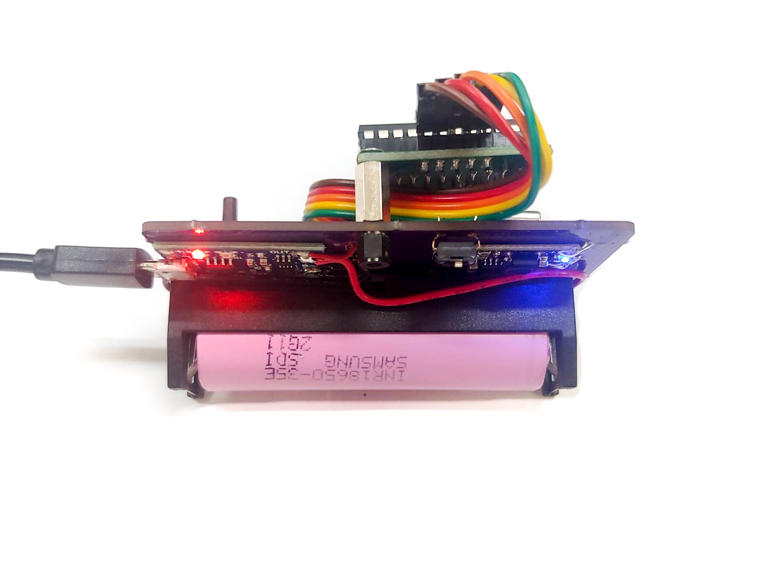
The final board is shown here, but described later more in detail. Given the improvisation of this board, no case is provided, and the PCB had many holes to test different assembly combinations. The most usable combination of the custom PCB, off the shelf power-management-system and display, led to this result:


Allowing it to be also plugged in, charged and/or used with a battery:
And in the video below the final result. It is implemented the abovementioned RTC clock with a tolerance of 10 minutes per year and the capability to set the time at the startup. The RTC will last almost 10 days with a single charge, and can even be kept attached to a power cord, with or without battery.
And if there are enough resources to code some “Hello World” animation, in this 1024 words RAM microcontroller, is not possible to have the RTC and an animation like this one:
To keep it on a desk, can look even cooler with the purple background coming from the charger. In fact, without a battery, all the energy is redirected to the system, and a heavy load will tricks the BMS in activating the red LED used to signal a charging in progress. The more the current required, the more red it is, and viceversa, is purple:
Curious to see how is working more in detail? Keep reading then! 🙂
The Hardware
The hardware is made essentially by the following parts:
- A display (with the MAX7219 controller)
- Power management boards (BMS+Charger+Regulator)
- Power consumption
- The PCB (with MCU and oscillator)
The display
For the display, it is used a cheap 64 pixels, 8×8 dot-matrix LED, driven with the common MAX7219.
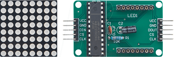
Each line in the chip memory of the display corresponds to a digit, and each digit can be serially loaded from the MCU. Therefore is “just” matter of working out a firmware for it.
Since the MCU has 64bytes of RAM, and experience tells me that some code here and there, written in C instead of assembly, will fill up the memory quickly, so a “compression” strategy is implemented. In fact, each digit uses half of the display, and allows the display to visualize a complete time tenths and unit (hours or minute) in one 8×8 matrix (see the TL;DR above for the result or the firmware section below for more).
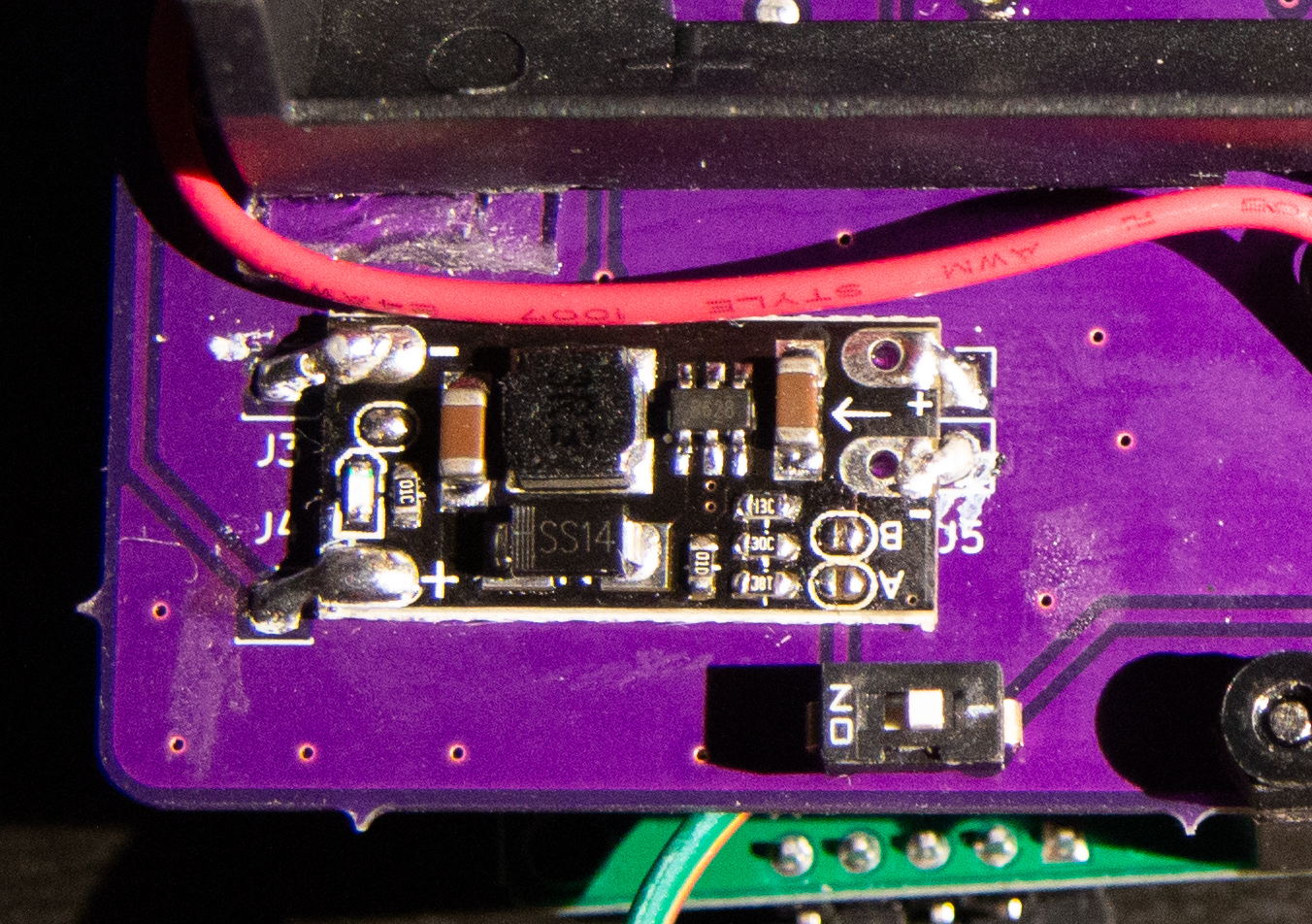
Power management
To use a single cell a protection circuit is needed, along with a charging controller. For this, a linear charge controller with protection chip was used, to charge up to 4.2V, and protect the cell from overdischarge, disconnecting at 2.5V. On this chip is possible to adjust the charging current, but unfortunately not the voltage thresholds. With a normal USB-B micro connector, the system can be powered via an external supply while also charging the battery.
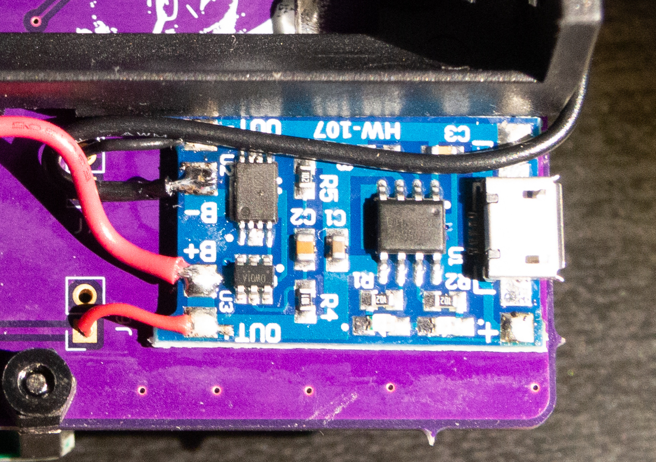
Then a switching booster is used to boost to 5V for the entire system. A power switch is inserted between the BMS and the booster, effectively shutting down the board when not needed.
Power consumption
A few words on the autonomy. The cell used is a standard Li-Ion 18650 cell, with 2600mAh (2.5V – 4.2V range). With the display in standby, blinking the 2 dots, alternates between 15mA (display and MCU consumption), and 3mA. In fact, when the dots are not shown, the display is actually turned off with a command.
So the average current is 9mA at 5V, or 45mWh and with an average cilindrical 18650 cell of 9.6Wh, the RTC can last up to 10 days with a single charge.
The PCB
The PCB was ordered via OshPark, for the classic purple soldermask – a side note, they did not sent anymore the classic stickers.

The PCB went through different assembly combinations, before the final desk version in the TL;DR paragraph above. Below, some of the incremental attempts:


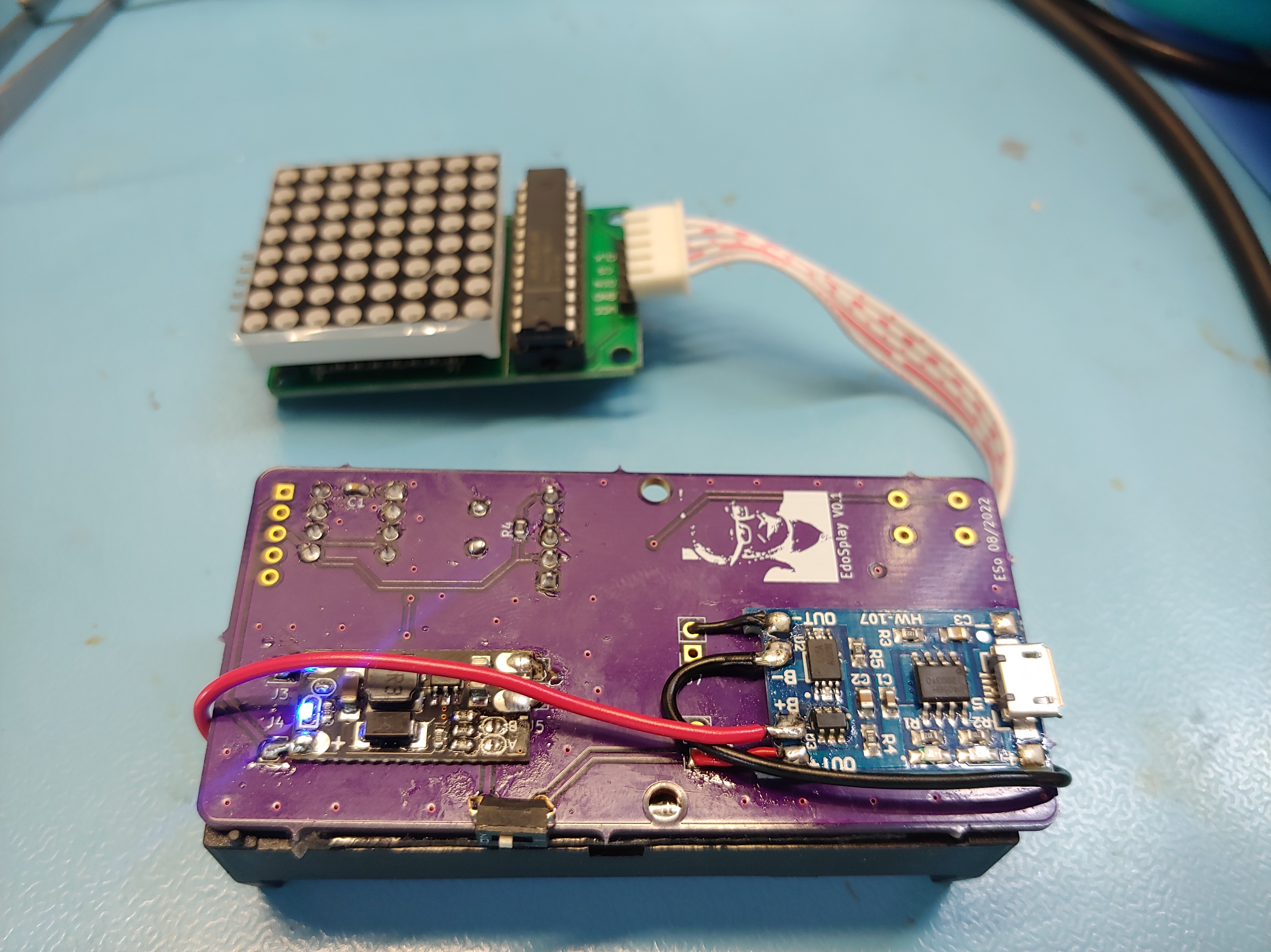
The PCB purpose was mainly to glue together the BMS and the regulator, while hosting the MCU, button, the oscillator and the connectors. The interesting part was on the firmware, due to the particularly small MCU.
The firmware
Firmware is made by the following sections:
- Bit banged SPI
- Character map
- Display configuration routines
- Charachter scrolling animation
- Timekeeping routines
- Time setting
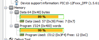
It was compiled using the proprietary XC Compiler from Microchip. The whole code took up almost all the memories, despite the optimizations of my algorithms and the compiler, yet still much of the code can be greatly optimized. This was the total memory usage:
Bit banged SPI
The SPI bit banged was needed since there is no communcation engine in this device. Luckily, is among the easiest protocol to implement, because is just a bit shifted to a pin, with another emulating the clock:

The asymmetricity in the delay takes into account the additional execution time after the CLK goes high. At 2^22 Hz divided by 4 of CPU clock (division due to the CPU architecture), the PIC12 is not very fast, and each instruction adds a delay, so the wait time was reduced to 1us to have simmetrical clock waveform.
Character map
The display itself is driven with the MAX7219, with no decode for any digit, so is possible to load any bit and directly show it on the LED array. This data is “handwritten” in a bidimentional array (for code readability mostly), inside the flash (ROM):

To save space and fit the 8×8 LED matrix pleasantly with 2 digits, a 4×8 char is made. To prepare an array to show, there is a routine that checks every part of an array received as a pointer, looks for the corresponding map (switch-case here is hidden for clarity), and assigns to a local pointer the selected character. Then, per each character, each of the 4 rows are copied individually to the display buffer:
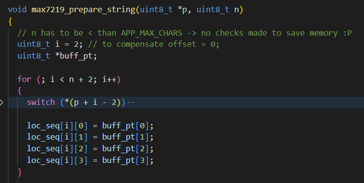
Trick: making a for() cycle for 4 chars will generate the same code size but with more data (RAM) as one more counting variable is needed, hence 4 the consecutive assignments of loc_seq.
Display logic and animation
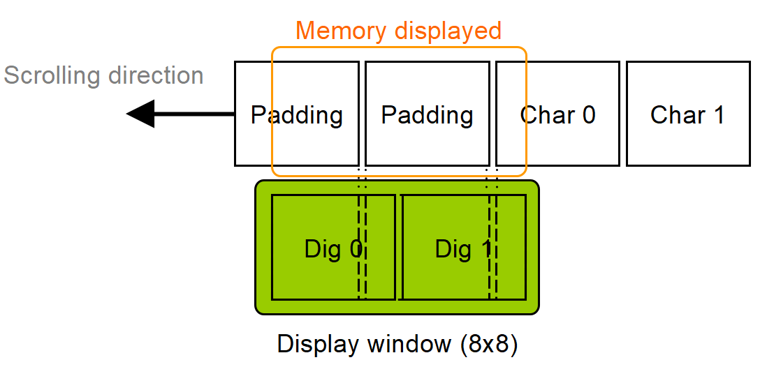
On the display are then sent 2 characters, filling all the 64bit memory of the controller, which contains the data with the characters desired. Though the initial idea was to shift the ROM pointers without using a RAM buffer, a map of pointer would have been needed, and in this case would have taken the same space if not more. So the real copy of characters are packed into a data RAM buffer. Also, to make the scrolling characters appear from the right side of the display (see video above), the first 2 characters are all initialized to 0 (padding), and then all 0 are sent to the MAX7219. This will effectively send a value of a “null” character, without actually using the character map.

Conversely, the shift is made by shifting the bytes of each character (which is made by 4 bytes) into the next one, and the last byte of the last character is filled with emtpy data, so is sent just 0. Then the data in loc_seq is shifted via the loc_segment_scroll(), and again the same loc_seq[0], loc_seq[1] are sent to the display, showing the character. This achieves the effect of the char disappearing on the left side of the display:
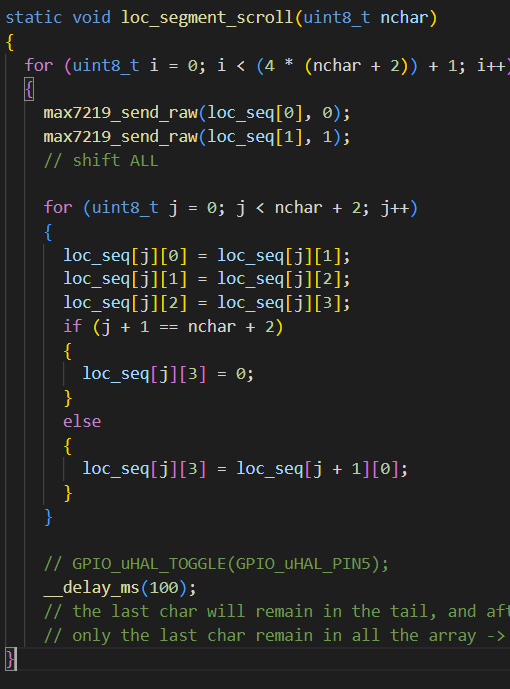
Writing the snippet above without the bidimentional array would have been a nightmare to handle and also to read the code, without any benefit. The nchar argument dictates how many charachters will be scrolled in the display, achieving a complete appearance and finishing with the display empty again.
Two loops are involved, one for counting the total nchar iterations, the inner one to shift the byte of each characther of the display buffer. The send_raw() will transmit the firts 2 bytes of the display buffer to the screen. The screen will only receive an area of 2 characters, shifted in the loc_segment_scroll(), according to the following logic, to create the animation:
Timekeeping routines
The core of the RTC functionality is an interrupt triggered every 500ms, handling the increment of seconds, minutes and hours. Since there is a 
- Clock division 4
- Prescaler 8
- Timer counting to overflow (up to 65536)
Meaning 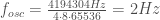
Also, cristal precision is around 20ppm, and in a month of 2678400 seconds, leads to a precision of:

Every 0.5s an interrupt is triggered, handling the timekeeping data – here a snippet of the code:
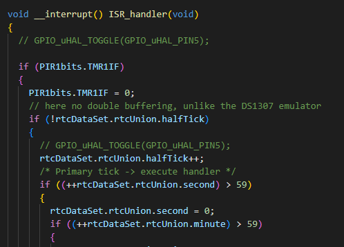
Trick: the data structure is here defined with the bit union:
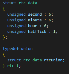
Where to save one byte, only 6 bits were used per variable (to be able to count above 60). Saving 2 bits per variable led to save one byte in total. In fact, second, minute and hour all take 18 bits, the halfTick signal is one, but is padded with additional 5 bits (24-19 bits), since 24bit is the next rounded byte that will fill the memory, being an integer of 3 bytes. Byte padding is needed since the MCU can only work in integer bytes, not fraction of them!
Trick 2: In this case halfTick could have also been 5 bit wide, but it would have needed a overflow checking to keep it between 0 and 1. Having one bit instead, allows to achieve this just by increasing the halfTick every time and save memory otherwise used by the overflow checking.
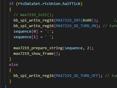
Trick 3: The main routine will just check the flag set in the background interrupt and show the double dots accordingly. But to save more code, when the dots are not shown, it is just send a turn off signal. Otherwise, two dots dimmed are shown. And well, this saves also a bit of energy too.
Setting the time
The limited size of the MCU also in pins, requires carefulness: only 4 pins are available, if 2 are used for the oscillator, 3 by the display, and only one remain for the user interaction. This is achieved via a single button.
The button is used for 2 functions, setting the time at the startup, and showing the time at user request. To set the time there is a startup sequence, that reads the button, and so the user has to follow the (optional) following sequence to achieve the time setting:
- Turn off the board
- Turn on while pressing the button and keep it pressed
- Wait the increment of the hours
- Release the button and press again within 0.5s
- A bright, double dot appear to acknowledge the switch to minutes
- The minutes will appear and start to increment
- When ready, release the button
- A dimmed, double dot will start blinking and the time is set
See demo at the beginning showing the time setting.
The setting code is in the following snippet:

Trick 4: to save further ROM space, for every single instruction that requires more space than a function call, a function was implemented.
For example, reg_init() shows the characters selected in the sequence array, and this requires some instructions (for details see the source code).

The reg_init() function also contain the 500ms delay, which is used as a delay for each number increment, and for the wait time selection between hours and minutes.
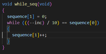
Trick 5: a normal approach to extract the units from the tenths in a decimal number is to use the “modulo”, for example,
unit = tenths_number % 10;
But the modulo is effectively a division returning the remainder, which is transformed into code executing it. This takes a lot of memory. So is implemented another algorithm, where is counting how many units are needed to be added or subtracted to change the tenths. The counted number, are the units.
The take away
This small project was a huge learning opportunity. Learning how to manage the time effectively, in order to go from an insipration under the shower up to make it real, was a big part. But also technically, it provided perspective on how much can be done with small MCUs. Future steps might be comparing the performance of the code with the open source compiler, SDCC.
For further info, check out the repository project on GitHub.
Most importantly, it was also a lot of fun and satisfaction. Enough to get fuel to refine the project further on, in the future. Sometimes, we “just” need to do it, as Shia LaBeouf might say.
