
In need of a new pair of headphones, I wanted to go more towards brands which were less anonymous and more reliable. As I needed a Bluetooth headset but also the Active Noise Cancellation feature for when I work or travel on a train, I wanted to give it a try and I found the Marshall Mid ANC t be the best price/quality/features for what I needed. I am an essential person, I did not wanted to pay for extensive features I will never use.

The reason I went with these specifically, were that the reviews were ok, the ANC is super easy to use and most importantly, it has both Bluetooth and 3.5mm jack. Drawback was a good, but not super ANC system, and is especially true when compared to others, like Sony. So that got me interested: how much it take with the modern technology to make a good ANC, from the manufacturer point of view? But then other issues that made me curious arise, completely unexpected: after a teardown with a little of reverse engineering, I am going to find why not only the ANC is not perfect, but the Bluetooth calls are simply bad in noisy environment.
A first look inside
With a bit of magic and adhesive peelings, we can go inside by simply unscrewing the ear cushions (I like that, they can be bought separately and replaced!) and just remove the 4 screws you immediately find. If there is a label, it need to be peeled carefully first.

By opening both of the speakers, we immediately access to the internal electronics.
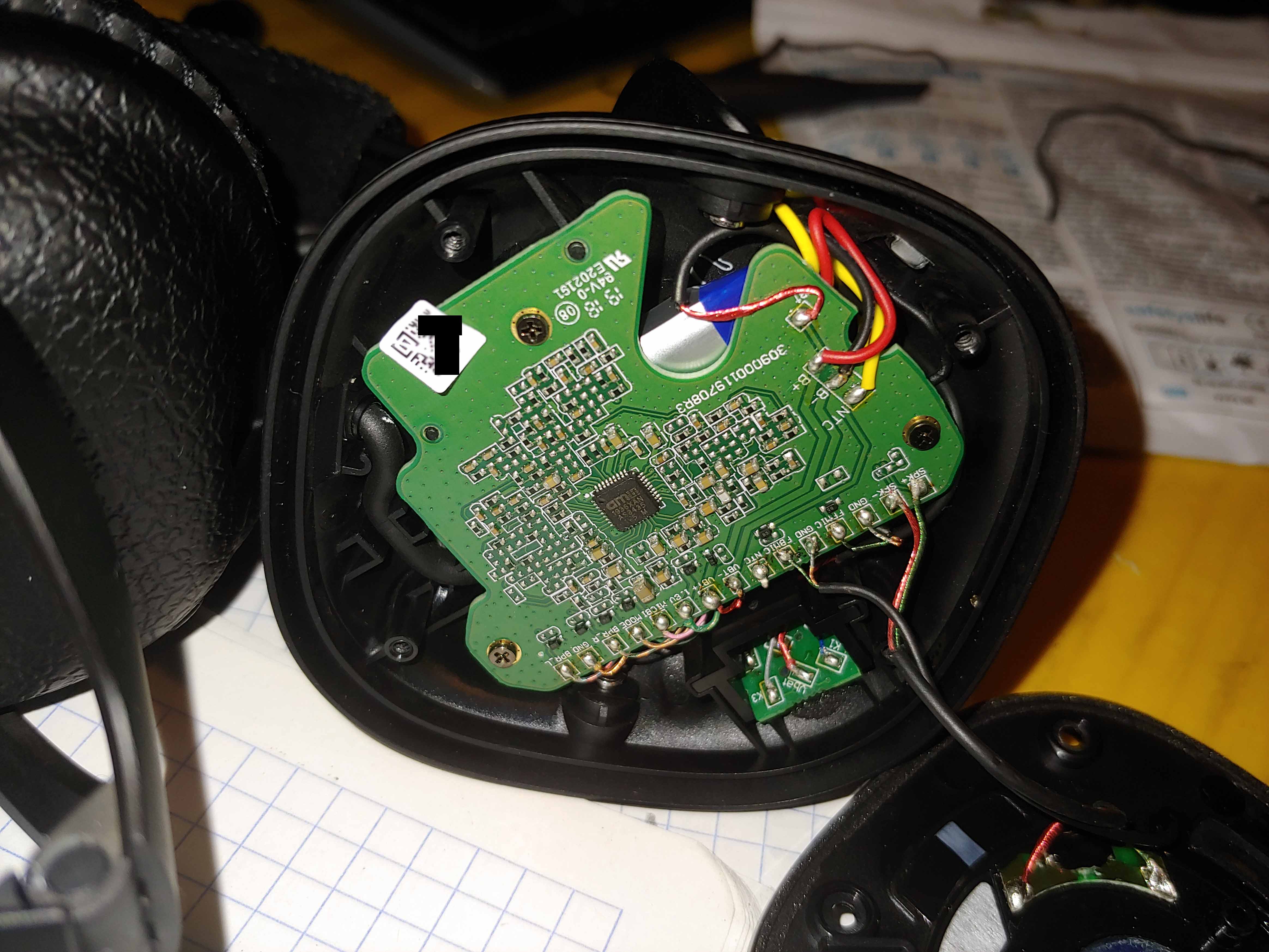
There are 2 main PCBs, one per speaker. Let’s start to analyze the left one and see what can be possible to understand from it.
How the ANC works
To understand what is inside, first is needed to have a rough idea of how an ANC system works in principle, as it will says a lot on the architecture used in these headphones. Therefore to make sense of the signals and connections, let’s dig first a bit more on how the ANC works in general, by looking at this diagram:

There is a “reference” and an “error” microphone, the system hear the noise outside, invert its phase and add it to the speaker. But why is needed an error microphone? First let’s understand that with a reference microphone only, is recognized to be a feed-forward architecture, where most of the processing is done by this phase reversal, and critical is the processing speed. The following reasoning is done after reading articles like he one from EDN and not only.
In fact, the sound travels at around 343 m/s, and for example with 3 cm distance from the reference microphone to the speaker, the ambient noise takes around 87 µs to reach the area of the speaker from where the reference microphone is placed. Since this IC is part of the analog processing ANC family from Austria Micro-Systems (AMS), there is an analog signal processing time which has to be faster than this. Obviously these are wild assumptions, but mostly to show the concept of the microphone displacement that has to be accounted. Mortal people don’t have any detailed info on this ANC chip, but given the fact the reviews and myself notice a good ANC effect only on low frequency noise, maybe is not much faster in reality. The analog filters, as also stated from AMS, are designed to not cut high pitch voices, to not hide important sounds. Is it a sentence to cover a bug and make a feature out of it?
The left speaker
If we look the outer shell of Figure 3, is consistent with the position of a feed-forward ANC microphone:

But by removing the ear cushion, is spotted an error microphone, positioned in front of the speaker, as in Figure 6:

From how the system is built, this turns out to be an hybrid feed-forward/feed-back ANC system: as the word implies, the feed-forward simply corrects fast enough the signal based on an acquisition from a source which is not the system output and forwards it to the system output. On top of this, the feedback listens back the sound from the speaker and, by comparing it with the sound input, it cancels out the difference.
This below is an enlargement of the headphone PCB. Is noticed a certain amount of signals, and the AMS AS3435 chip itself.

The passive components are probably related to the filters that are implemented externally, like in this diagram, directly available from Austria Micro Systems website:
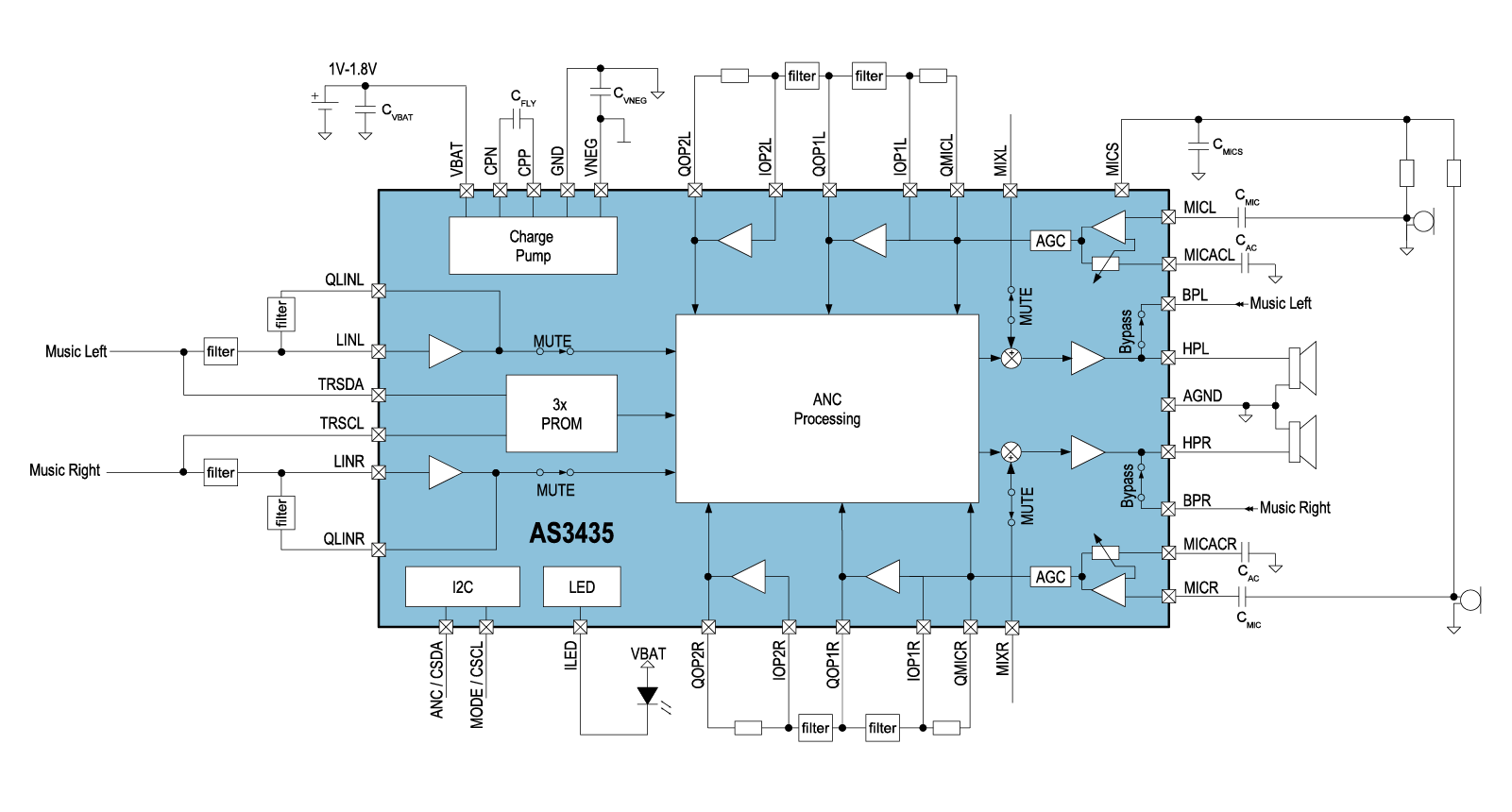
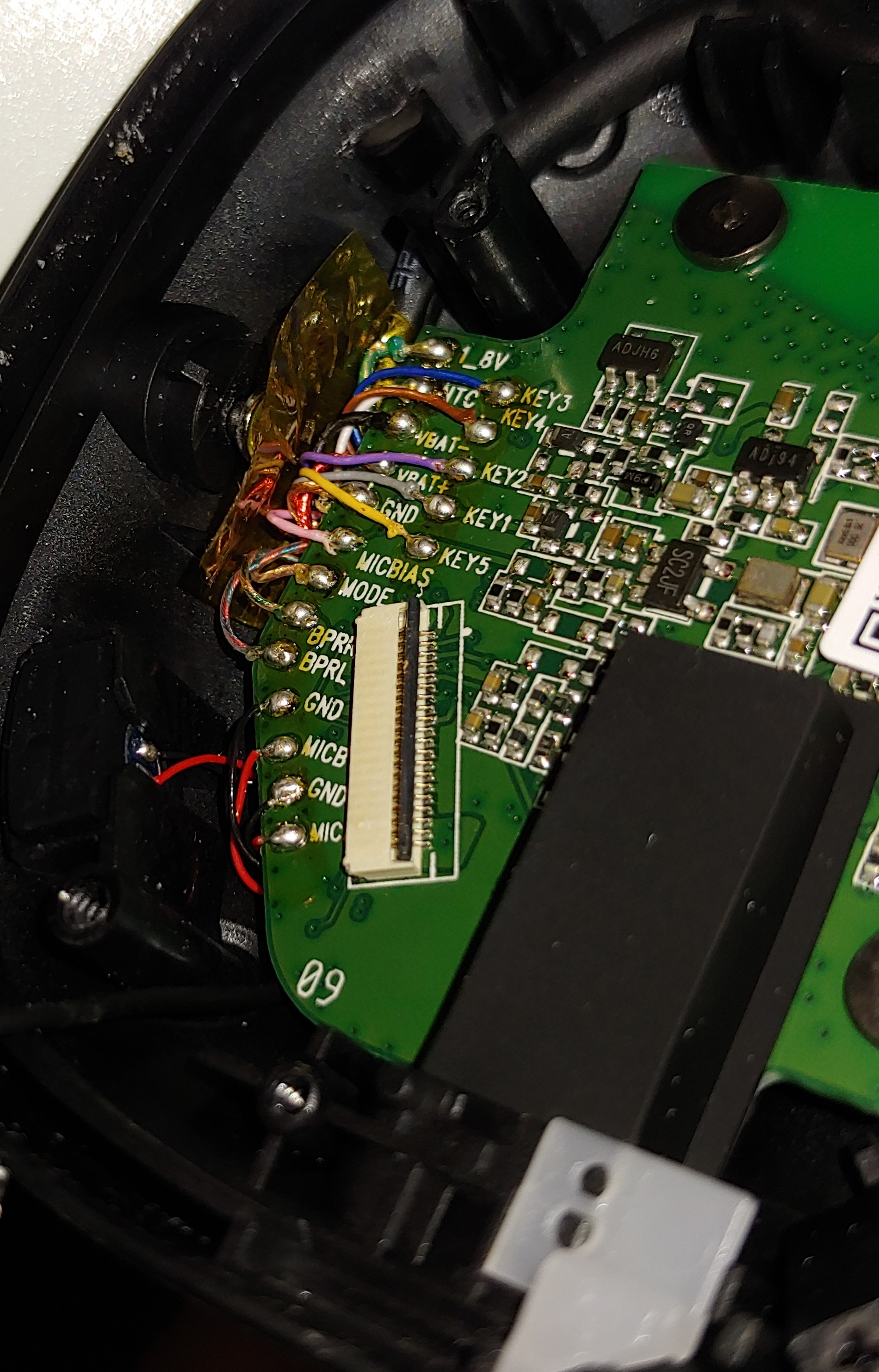
There are some labelled signals, which will be useful also for overall understanding of the system:
- SPK+: speaker output phase +
- SPK-: speaker output phase –
- FFMIC (and GND): the feed-forward microphone
- FBMIC (and GND): the feed-back microphone
- NTC: the NTC connection from the battery
- VBT+: battery terminal +
- VBT-: battery terminal –
- 1.8V: supply for the ANC chip
- MICB: microphone bias, likely used to bias the ANC microphones
- MODE: from other available datasheets of different models, this seems to be the input used from the ANC switch, bypassing the signal processing when the ANC is turned off, shorting the audio input straight to the output
- BPR_R: this is where the signal from the input is bypassed to the output when the ANC is off, for the right speaker
- BPR_L: same as the BPR_R, but for the left speaker
In the headphones, there is 1 channel and 2 microphones. In the schematic, 2 channels and 2 microphones (one per channel). Could it be that the 2 microphones are combined in a feedback/forward pair dedicated to a single channel? Or the diagram available is completely wrong compare to what’s inside the real AS3435? The specification page states:

Which means the device can be used as a stereo (like in figure 6), on in mono BTL (bridge-tied load). The BTL essentially get the 2 stereo input fed with two signals reversed, and used their output to load a single speaker. Also, the topology of the ANC seems to vary, which makes me think that in BTL mode, the hybrid configuration is supported. Quite flexible!
Few time based acquisitions can reveal bandwith boundaries
By measuring the feed-forward microphone and the signal on the speaker, it was possible to find a trend of an increased phase shift with increased frequencies. Measurement is done by having no sound input and generating different ambient sounds of varying frequency, by playing tones on a speaker. With a relatively low frequency, here is the result:

The purple signal picked by the microphone does not match exactly the inverted amplified signal at the speaker terminals, but they still seem quite in perfect phase opposition. To see this further, I run the same acquisition on a higher pitch signal:

It is evident what is experienced at the user level. Now we see how higher pitch sounds tends to not be closely compensated, where here seems to be a 400us delay, around 60 degrees mismatched from the perfect phase inversion. I believe this shows the bandwidth limitation. With my headphone on, reproducing sounds from 600 Hz and above, the cancelling perception is way less than sounds played at frequencies lower than 400 Hz. In the Figure 8, the high frequency component is around 500 Hz and the 60 deg phase shift seems enough to “leak” sound which is not out of phase.
More specifically, from a theoretical point of view, if we simplify and don’t consider all the components of the sound in Figure 8 but only the foundamental at 500 Hz, what I hear is:

Where A is an amplitude with units matching the context, in this case can be a voltage, or while hearing can be Decibel (relative to sound generated pressure, feel free to use Wikipedia for various definitions), and the cosine of the phase shift is a constant as well. 
Back on the teardown.
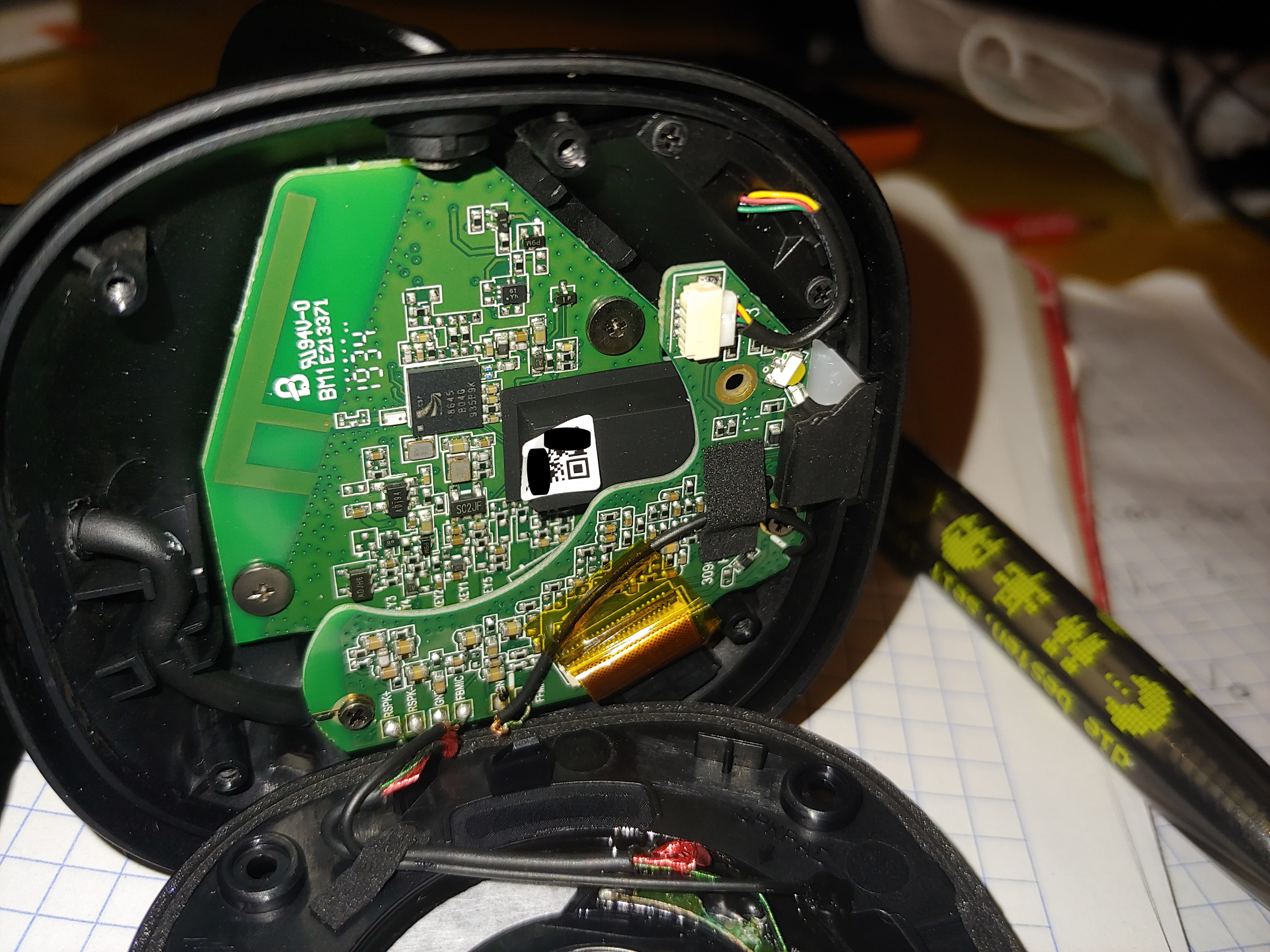
The right speaker and the main SoC
On the right part is found the main SoC. Here is highlighted its PCB. By looking at this side, the whole architecture is much more clear.

The SoC is a Qualcomm CSR8645, a full fledged Bluetooth controller and DSP system, completely separated from the Active Noise Cancelling system, shown later on. It is also VERY common among major Bluetooth devices and DIY projects. Around the SoC are present some passives and at least 3 LDOs, likely for the 1.8V, the bias of the microphones and maybe something related to the SoC Qualcomm.
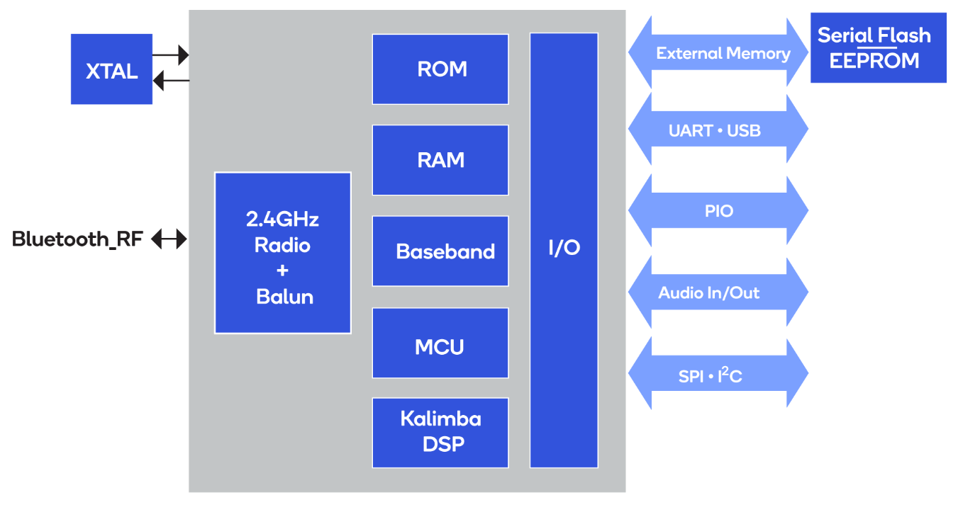
The PCB contains mostly passives for GPIO interfacing going on the other headphone for the user buttons, and some active regulation for the SoC, completed with the RF Bluetooth interfacing. The SoC contains a lot of features, copied here from the Qualcomm website:
- Bluetooth 4.0 specification compliant
- Flexible ROM-based platform with fully configurable MMI and tool chain
- Support for various profiles including: HFP 1.6, A2DP 1.2 AVRCP 1.4
- 80MHz Qualcomm® Kalimba™ DSP with integrated multipoint A2DP and HFP audio applications
- 2-mic cVc 6th Generation voice processing technology with wideband speech
- Audio tuning suite with audio enhancements and 5-band EQs
- Internal ROM, serial flash memory and EEPOM interfaces
- aptX, MP3, AAC and SBC audio codecs
- Reference speaker and headset applications pre-loaded on the ROM
Since most of the features are used, including the aptX codec, I wonder what is the issue of the background noise during Bluetooth calls. Seems that the “cVc voice processing technology” is confusing background noise for a voice source, and making it loud and clear, especially during moments of silence. Searching around I also find a description like “noise suppression and AEQ”: and what I experience during a Bluetooth call, it might be something related to a bad audio equalizer settings. I guess that might be the culprit: it could also be a bad calibration at Marshall.
I say “calibration”, since the SoC is a non-programmable RISC processor with a pre-load set of Bluetooth and audio application which can be customized with no firmware development. Settings are loaded in a internal memory.
For reference, I even found that is possible to buy a CSR USB-SPI ISP Bluetooth programmer like this one:

Also, towards extinction, the software exists to interface with this tool, I suggest to make a search with keywords like “CSR Bluetooth Module Programming”. Working out AEQ settings and the like, might be exactly what the manufacturer is doing. In this case is Zound Industries, selling under Marshall brand. Now, I would not try to poke and potentially damage my headphones, but technically is possible to play around and see what is possible.
The ANC is on top of the main PCB, and can be removed:

On the main PCB we can identify the main connections:
The signals labelled are the following, and most of them are the same described previously:
- 1_8V: the supply needed for the ANC chip on the other speaker
- NTC: the battery thermistor coming from the other speaker
- VBAT-, VBAT+: the battery terminals, from the other speaker
- MICBIAS: the bias of microphone for the ANC microphone on the other speaker
- MODE: to change mode (enabled or not) to the ANC chip on the other speaker
- KEY1…5: the signals from the control know on the other speaker
- BPRL/R: the bypass mode for the ANC on the other speaker
- MICA/MICB: the bluetooth microphones
There is also a set of wires, named MICA, MICB, with reb/black wires. In this speaker there are 4 microphones: 2 for the ANC, and 2 for the Bluetooth audio: MICA/B are the SoC Bluetooth ones. Therefore, the MICBIAS is likely to be for the ANC chip on the other (left) speaker. The circuitry on this PCB with the Qualcomm SoC seems also to contain the 1.8V regulator for all the ANC subsystems. Also all the battery charging, NTC, user keys and control modes (for ANC active mode) are all travelling between the two speakers.
Further look into ANC of the left speaker, to the USB and LEDs
While understanding where the BPR signals are going, like BPRL/R for the ANC bypass mode, something was noticed. On the previous left speaker, there was no clear sound input. Further understanding is brought by looking at the AS3435 on the right speaker – here with the ANC correctly assembled:

Where this PCB holds also the USB connector:

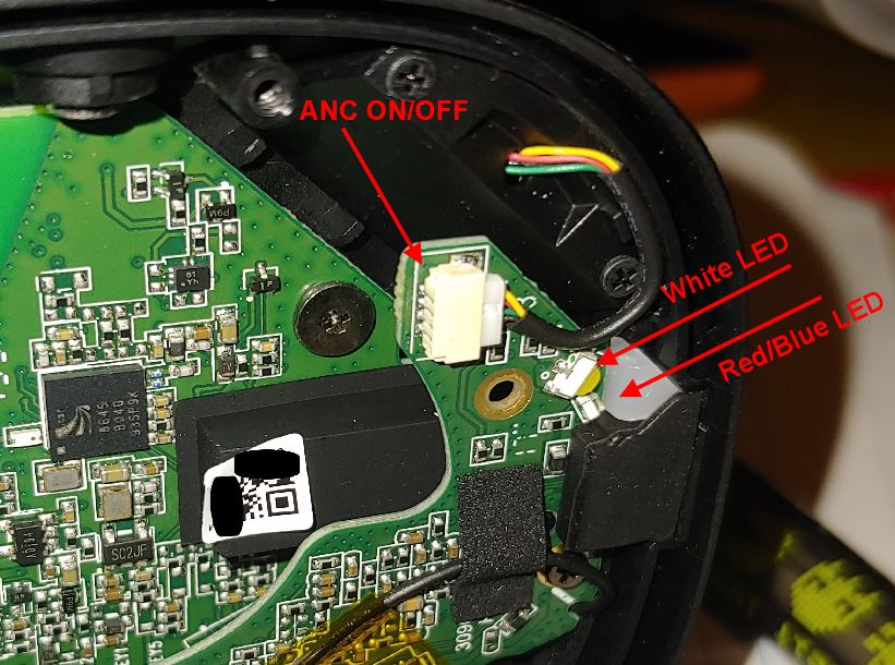
And on the other side, the LEDs, connected via the FPC to the main PCB, can be spotted:
The only audio connection going to the speaker, comes from the ANC board, and since the sound need to be mixed in the ANC, this makes sense. But when the system is not active, the Qualcomm SoC or the jack should drive the speaker. In the previous Figure 5 of the left ANC, there is no clear audio input. The only audio coming from the main Qualcomm SoC board, are the BPR_R/L. This is likely the same for the right speaker. Also, the ANC chip is on the other side of the ANC PCB.
The mechanism can be understood by checking an equivalent AMS part with a public datasheet, like the AS3418. It is possible that the BPR/BPL, are routed to the input of the ANC in BTL mode, and when the user switch change to the ANC OFF mode, the same signal is shorted and still provided in BTL mode, like in figure below, red arrow.

The main PCB then would take care to redirect the signal from the jack to the speakers, or from the SoC.
The back of the main PCB (with the Qualcomm SoC)
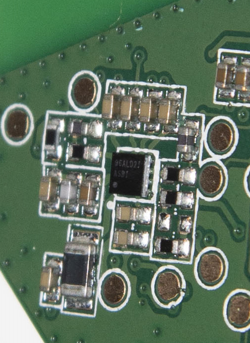
There are still some more components on the other side of the PCB containing the SoC:

Where can be individually spotted some more or less clear components. One named 96ALD21, which seems some sort of microcontroller – to handle the wake up functions?
While others more obvious:

The one marked as AGQ could be the linear regulator for the Li-Ion battery – due to the big sense resistor probably to monitor the current, although the SoC should contain already the feature to handle the battery. The 6L02E instead is a dual op-amp, and since the red cables going to the BLE microphones are close by, it can be their conditioning to the SoC interface. Another component below the op-amp, looks like another LDO, probably for the biasing of such microphones.

The last component found, but not the least, is the flash memory to support the SoC, likely to hold extenal custom sounds and the like. It is a 4Mb (512KB) flash on a SPI interface to the SoC, probably just enough to hold plain sounds for the various notifications, and probably to hold also some custom settings.
Conclusions
At the time of writing, 2 years after having being released, these headphones are not produced or officially sold anymore. I bought them one year ago, as were still available, and also discounted, while having all what I wanted. Not many headphones are small (on-ear), with simple ANC switch, BLE and with 3.5mm jack. This pair of over-the-eat headphones are great, the ANC works reasonably to filter out background noise, for example when on a train, low frequency echoes in crowded places, without eliminating voice, altohugh are still getting attenuated. It still give the feeling of being “isolated” from the outside world, which is what I wanted. But since the controls are all wired, there is no check in between for automatic shutoff, therefore I forgot multiple times the ANC on, getting the battery depleted in 30h or so.
The main, if only, drawback are the Bluetooth calls. The algorithm really fails and boosts up all the noises around when I don’t speak, which means I need to be in a relaive quiet place to speak, or I need to mute all the time when the other person is speaking. So, forget using BLE while cycling. On the other hand, the BLE interface and the Bluetooth connection makes them awesome for listening music, watching movies and control the playback. But a big plus, is the chance to always use the external 3.5mm jack with audio and microphone, allowing to have the headphones battery depleted, or making calls without the issues of the Bluetooth audio filtering.
The overall assembly allow them to be fixed quite easily for minor repairs and replacing the battery, and this is a big plus. The maintenance of the wearing parts is possible, at least for the ear cushions, which can be bought separately. This is not a commercial review, just my opinions, and the primary goal was to see how was the complexity of such headphones. Being able to disassemble them without breaking anything, was much appreaciated.

Ever tried resetting those headphones..?
The procedure Marshall gave me doesn’t work. I can feel the switch toggle (click) but that’s it.
I want to reset them and see if that will get solve the problem I have while I turn them on…problem being that it takes over 10 seconds for them to come on 😦
LikeLike
I don’t think you can really reset them, for sure not the tuning parametersI think your issue is a common one among Marshall headphones: they don’t turn on, like mine as well. You need to keep for 3+sec, 3 times, then it turns on. Maybe I’ll try to fix it and write a small post about it…
LikeLike
Official fix from Marshall:
The reset button for the Mid headphones is located in the headphone input.
Please use a paper clip or toothpick to hold the reset button for 2 seconds.
It is best to attempt the reset with the headphones charging. This way,
you can verify that the reset has occurred, as the LED will turn off.
LikeLiked by 1 person
Thanks! I thought it was a button to detect the jack! Still, I don’t think a reset will do anything, as seems an HW problem to me, but I will check anyway.
LikeLike
Hi, thanks for your review, is really nice and helpful.
I have a problem with mine since yesterday.
I was listening to music and the headphones shit off suddenly. I thought the battery was dead so I put the to charge, and later try them again. It lasted like two minutes before turning off again and now is not possible to turn them in again.
I tried resetting but nothing happens, and when charging the led is not on. I think the problem could be the battery but the ANC works fine.
If I turn them on while connected to the charger they turn on and inmediately turn off.
Also, the knob is not working properly, so I can’t turn the volume up or down. Do you know if is relatively easy to change the knob?
Thanks in advance and sorry for the long question.
LikeLike
Hi, it looks like you have a battery trouble, and need a change. The ANC can work also if the battery has issues, but the Qualcomm chip an detect an issue and shut down. The ANC chip in fact does not have this control functionality.
LikeLike
Such a piece of work, amazing! Thank you for sharing! Do you still have this headphones? I need one superbasic size for design but can’t find it anywhere online. Could you please help? The width(or heigth) of the enclosure measured on the pad attaching surfacehttps://enricosanino.files.wordpress.com/2021/01/wp-1610826776699.jpg
Thank you in advance!
LikeLike
Hi, thanks for the comment, I appreciate it!
What do you need exactly? I still have them!
LikeLike
Thanks for your answer! This two dimensions, if possible)
https://ibb.co/PG7j94h
LikeLike
45mm and 67mm
LikeLike
Hi Drew, I’d like to know what your design is, if it’s no secret. I’m doing a mod of these earbuds, too
LikeLike
Hello. The headphones (Marshall MID ANC) operate in mono mode (the right channel works, the left channel does not work in stereo mode). What could be the problem and how to solve it?
LikeLike