

There are many articles that explain embedded software, bare metal programming, and architectural design, providing a lot of practical tips. The great majority of projects, particularly those that require quick but nice prototypes, are based on Arduino. However, starting an Arduino project seems not to require any theoretical knowledge of firmware architecture, bare metal, and sometimes not even general embedded knowledge.
Nevertheless, the reality is that this knowledge is still fully required. Someone else has taken the effort to learn it and has hidden the architecture, interfaces, and other complexities in a piece of software called framework. This framework is actually part of the firmware itself, but it can also extend as a set of tools outside the code itself.
Although there may be different definitions, a framework can mostly be anything that supports the user in writing the firmware of the application, including debug, testing, build chain customization and ease the porting to different platforms.
To understand this better, let’s see how a framework can help us set up the “Hello World” of embedded systems: toggling a GPIO.
The “Hello World”, or toggling a GPIO
When starting a project without any support, the developer must choose a development environment, set up the build chain (although an IDE of choice might do this automagically for simple projects), configure the debugger, find a way to program the MCU when the firmware is ready, and so on. Then, the developer has to, obviously, writing the firmware itself. This includes opening the datasheet, read about how the GPIO works, and code the behavior required for the interaction, often by directly writing to exposed memory mapped registers. This approach is considered to be extremely bare metal.
An example of code that would send a signal to the GPIO for an average STM32 part consists of the following lines:
RCC->APB2ENR |= RCC_APB2ENR_IOPBEN; // enable the clock of the GPIO
GPIO->CRL = 0x000000C0; // set the pin as output, push-pull, full speed
GPIOB->ODR |= (1 << LED_PIN); // set the pin to logic high
Assuming that the first two lines can only be run once, this code example is not exactly readable or worthy of respect from peers who need to review the code, nor is it portable. Therefore, one might consider grouping the odd lines into a function, as follows:
gpio_init();
gpio_set(LED_PIN);
But there are at least 2 problems with this:
- Is just more “readable”, but not self-describing, and is not portable. One still need to change the entire code if changes MCU, or even just the pin configuration.
- The LED_PIN rely on having setup the correct GPIO port on the MCU. If in the gpio_on() there is another GPIOx port, the final command goes to the wrong register.
So at a very basic level, there is the need to make portable the pin mapping, and also the configuration, in case different pins need to be used and avoid cutting traces on the PCB, if you know what I mean.
Using a framework
It is now understandable what the main requirements of a framework to support the user code development are:
- Being capable to enforce descriptive features – am I able to understand what is going on by looking at the code?
- It shall be portable
- Each pin call should unequivocally call the intended pin (obviously, right?)
The fact that these requirements come from just a superficial check on a GPIO port, makes them even more obvious. Let’s see now a real implementation of how really obvious the implementation can be.
A famous framework
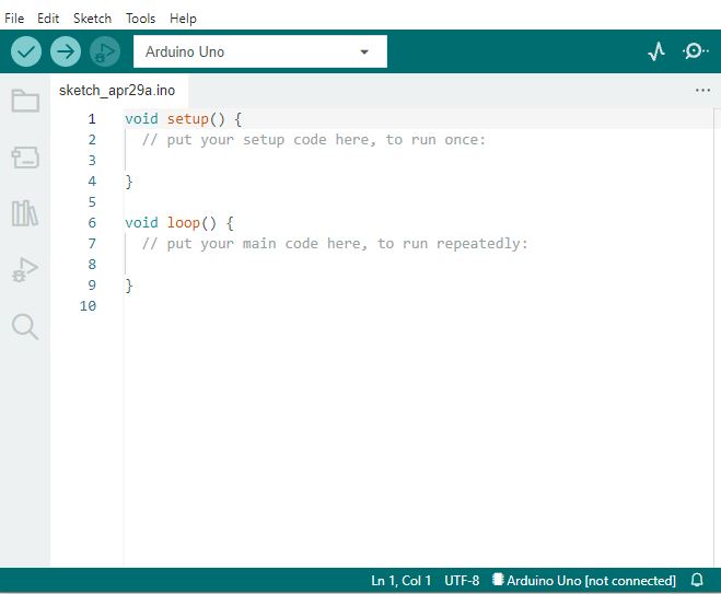
At the beginning, I mentioned Arduino not by chance. In fact, it is one of the most famous framework that encompass a set of API, HALs, IDE, toolchain and so on.
And by just focusing on the code, there are many things happening under the hood, but this can be discussed in another article.
For now, let’s consider the GPIO handling. If a user need to set a GPIO high, is just needed to implement the line to initialize the pin, and then there is the control itself:
pinMode(LED_PIN, OUTPUT); // init
digitalWrite(LED_PIN, HIGH); // control
The approach is very straightforward and easy. An inner mapping connect the number to a unique pin. A system like that might work for most of the needs.
But with this framework, the pin number corresponds to a board pin, not the MCU and this can be a problem if we need to keep the code clear, but ported on a different board. Maybe even part of the framework need to be adjusted, not only its configuration. That means a lot of debug before releasing any new firmware.
And if the pin needs a different configuration, for example we need to activate a pull up? Or for EMC reasons we need to smooth the transition speed of the pin itself? Is possible, but we go back to the bare-metal approach to hack together a solution in order to configure the registers unsupported by the framework.
Another example showing how a functionality is limited to the framework is a PWM output. A PWM needs a specific combination between a timer, an output compare circuitry and a GPIO. This is usually handled mostly in a timer configuration, and a small part in a GPIO. With Arduino, to output a PWM signal we just need to do:
pinMode(LED_PIN, OUTPUT);
analogWrite(LED_PIN, value);
What value is, this depends on the board and how the driver is configured. Sometimes it uses a PWM with a given timer with a prescaler and counter configuration hidden. Sometimes is a real DAC. If we need that timer, of if we need to adjust the PWM frequency – which is an important feature sometimes – again, we must go bare metal.

So in this case, if we need to change the PWM frequency, we should change the prescaler for example, breaking the HAL:
pinMode(LED_PIN, OUTPUT);
TCCR2B = ((TCCR2B & 0xF8) | 0x01); // for complex projects, this is bad and not portable
analogWrite(LED_PIN, value);
This tells us the main disadvantage and important aspect when using a framework: we are limited by the framework capabilities. Otherwise it become an additional development effort to actively extend the framework and integrate our solution. Anything done differently will, in a way or another, “break” the architecture or some clean code principles.
A possible clean solution
If the goal is to deliver clean code, properly designed, capable to support complex projects, then we must use a framework that will allow for such needs. If this approach brings complexity on one side, on the other, we gain in flexibility. But most importantly, we want the following features:
- Modular, new components can be added without changing others
- Scalable, the same components can be replicated to adapt to various use cases
- Testable, since it can be complicated
- (quasi) Object-Oriented, otherwise it looses the potential simplicity, once is developed
- Easy to use, since I am not a guru
- Portable, otherwise would not makes sense to a general framework in the first place
- With strict coding rules, almost algorithmically written (auto-generation and co-pilot potentially useful)
The GPIO example
Let’s see the GPIO concept again with a more flexible encapsulation approach, starting from how a modern GPIO works.
A pin is not just a digital input or output, but it can be:
- An output push-pull
- An output open drain
- with power control on the driver to change the digital transition speeds for EMI and consumption reasons
- it can read itself back
- An input with pull up and pull down
- An input comparator with hysteresis
- An analog input,
- An input for an oscillator
- ecc…
If any or most of this should be taken into account, then is better to have all the configuration under our view. An approach would be to have a configuration file with the names of the pins actively used in the project:
typedef enum
{
    DEBUG_LED,
    LED_PIN,
    CONF_GPIO_ENUM_UNUSED
} conf_gpio_e;
So we have all the pin used under our nose. The unused ones will be initialized in a predetermined state by the framework. Then, the actual configuration of the used pins can provide all the complexity needed in a clean way:
const gpio_hal_cfg_t gpio_hal_conf[GPIO_TOTAL_PIN] =
{
    {  .pin_enum = DEBUG_PIN,
       .port = GPIO_HAL_PORTA,
       .pin = GPIO_HAL_PIN_8,
       .mode_pull = GPIO_HAL_DRIVE_PP,
       .mode_io = GPIO_HAL_MODE_MUX_50M,
       .val = GPIO_HAL_VAL_FALSE
    },
    {  .pin_enum  = LED_PIN,
       .port = GPIO_HAL_PORTB,
       .pin = GPIO_HAL_PIN_13,
       .mode_pull = GPIO_HAL_DRIVE_PP,
       .mode_io = GPIO_HAL_MODE_OUT_10M,
       .val = GPIO_HAL_VAL_TRUE
    }
}
Here there are couple of configuration combinations. These are all stored in custom types, to avoid any confusion, compilations warnings and wrong casting. Depending on the driver type, if the struct can use const attribute, we make sure (unless we to explicit trickery) no one change them at run-time. Making a struct allow to simply ignore a parameter if a given hardware does not support it. These parameters are the following:
- .pin_enum
- The enumerator used to identify unequivocally the pin represented by the enumerator itself
- .port
- Here the complexity starts to unfold. The pin is normally part of a hardware, called “port”. The port can interact with the internal CPU or DMA, and can control the pins individually. So is fundamental to indicate which one it is. Since this apply to most MCUs, also this can be abstracted and made it portable
- .pin
- This is the physical pin intended to be mapped with our pin enumerator pin_enum, and is referred to the pin of the MCU’s physical package
- .mode_pull
- This is the mode that implements the pull type on the pin (up, down), to adapt it to the specific application
- .mode_io
- This mode makes the pin an input, an analog pin or an output at different transition speeds.
The reason why was decided to split a port from a pin was related to having such separation in most MCUs, and therefore mapping and porting easily the configuration between different hardware. In fact, if we analyze different MCU GPIOs, we notice all of them has this organization:


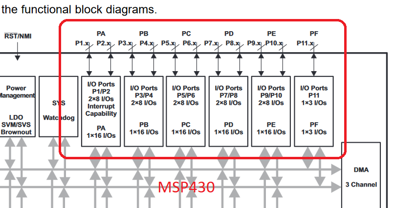
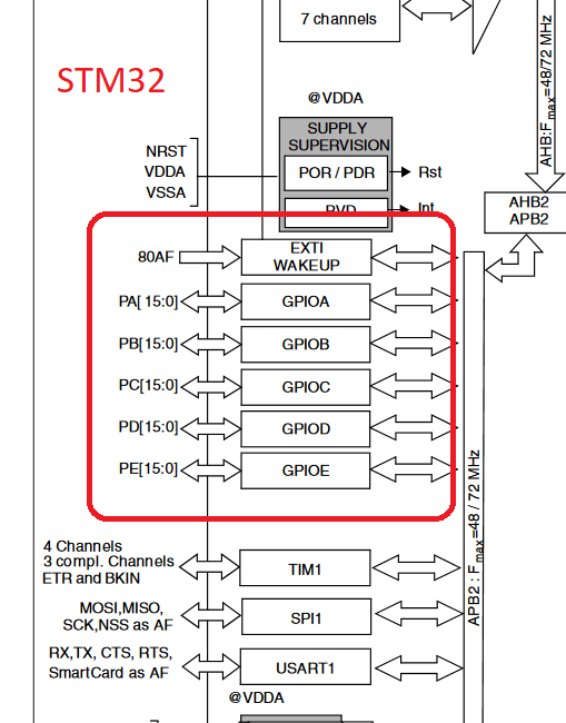
These are a couple of 8-bit devices from different designs, which usually don’t follow any standard between them, the Microchip PIC18 and the SiliconLabs EFM8. Then a 16-bit TI MSP430, and a 32-bit ARM based STM32.
Note also how there is a structure in the naming. For example, there are different modes of the pin, one could be a pull configuration mode, another could be a in/out configuration. In these cases, the name follow a hierarchical approach: mode_pull, and mode_io. The user, when reading the code, will always know what the line is about, without any comments required.
Also the enumerators and constant adhere to this: GPIO_HAL_DRIVE_PP is related to the GPIO driver of the HAL, it implements the DRIVE type selection, with the PP (push-pull) selected.
The final user code
Now let’s see how is the usage after the configuration. The initialization would be made via a single handle containing all the pins information:
const gpio_hal_cfg_t*  gpio_startup_config;
gpio_startup_config = Gpio_hal_conf_get();
Gpio_hal_init(gpio_startup_config);
Then, with reference to the configuration above that uses the LED_PIN as Port B13 of the MCU, the GPIO can be used with:
Gpio_hal_write_value(LED_PIN, GPIO_HAL_VAL_TRUE);
In this way the use remains simple, almost Arduino style, but with the pins are unequivocally mapped to the MCU, and it is completely portable to different architectures.
Also, by following the principle of framework confinement, any unused enumeration of the pin will be discarded by the interface automatically, and any undeclared pin will not allow the compilation. Finally, to guarantee control on the compilation, every parameter has a custom type. In fact, the function declaration above would be:
gpio_hal_err_t Gpio_hal_write_value(conf_gpio_e pin_enum, gpio_hal_val_t val);
So it is virtually impossible to touch a non configured interface, wrongly pass numbers, convert wrong data types, and so on, while keeping the code portable and testable.
Conclusion
We saw briefly why can be important having structured code when dealing with hardware interfaces in a microcontroller, especially when portability would be a future concern. But this will also improve readability, error detection at the physical interface, modularity also at the logical level, and compatibility with a common code rules compliance.
But the most important take away is to never use numbers in your code, and that to rely more on enumerations and defines never hurts.

glorious! 102 2025 RGBW Controller ASIC, part 1 – Tools used, FPGA design draft and where to start for making an ASIC gratifying
LikeLike