
I have some kind of interest in electronic projects, whether hobbists or a professional ones, which are based on standard and always available sub-components. Those always available parts are also called jelly bean components, like resistors, capacitors and cheap basic parts, like op amps (including in my opinion also LM741, LM324, even TL081 and the like) and other general purpose analog chip like the NE555. But the market is fully fledged with alternatives also for power supplies, with very highly integrated parts, for not very integrated wallets.
Maybe this is why my simpathy goes for basic building blocks, which are requiring to think more, in order to achieve something which reliably works and not being dependent on a single supplier and the moods of the market. So pondering about this, I started to be curious about the history of switching converters, on how smooth or quick was the passage from the early devices, to nowadays.
The early days (1930 – 1960)
When considerable amount of power was required, the efforts of theoretical research for the sake of efficiency became real. The technology around that concept of power efficiency, is the switching (or chopper) regulator. In fact, the switching concept exist since 1930 but were used “commercially” in the 40s.
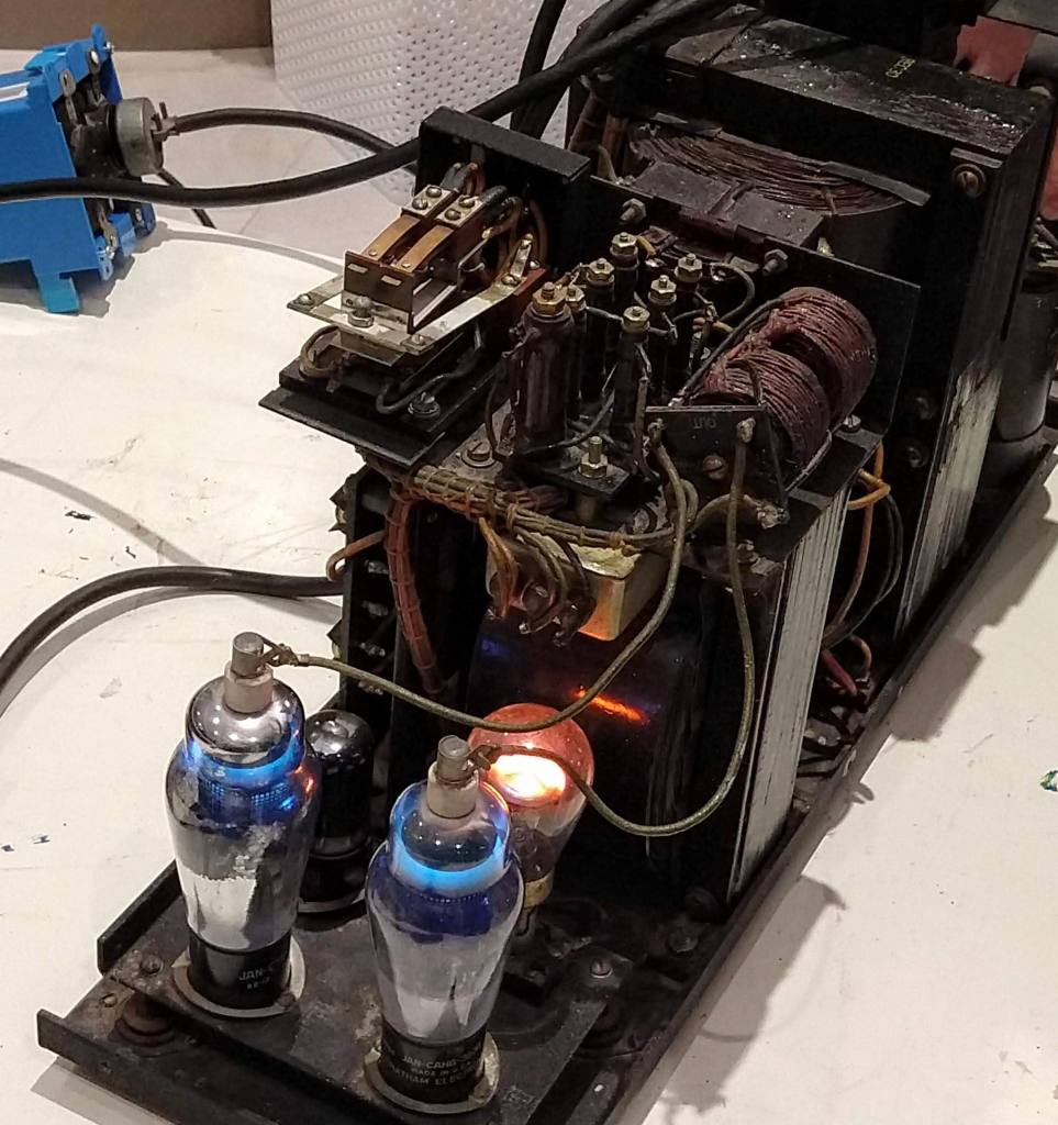
A small “switching” power supply, using vacuum tubes technology was adopted for the TeleType Model 19, even though it was more a “dimmer” that a switching regulator, chopping the input AC voltage and rectifying it – actually was an SCR power supply.
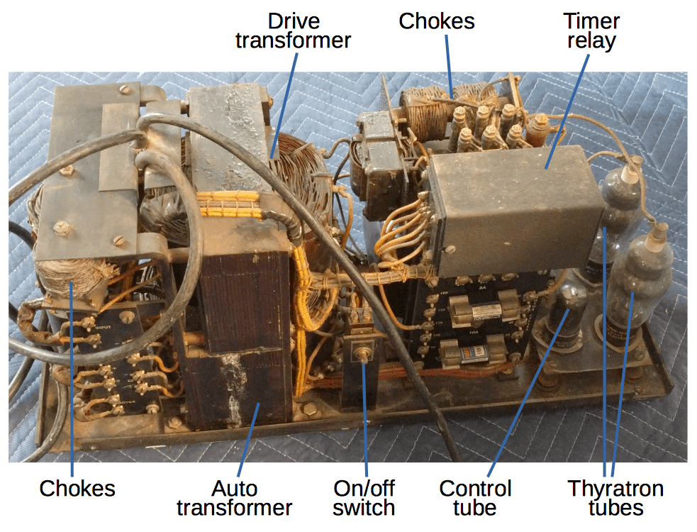
And this was the schematic, just to give a comparison meter with the more modern solutions listed later:
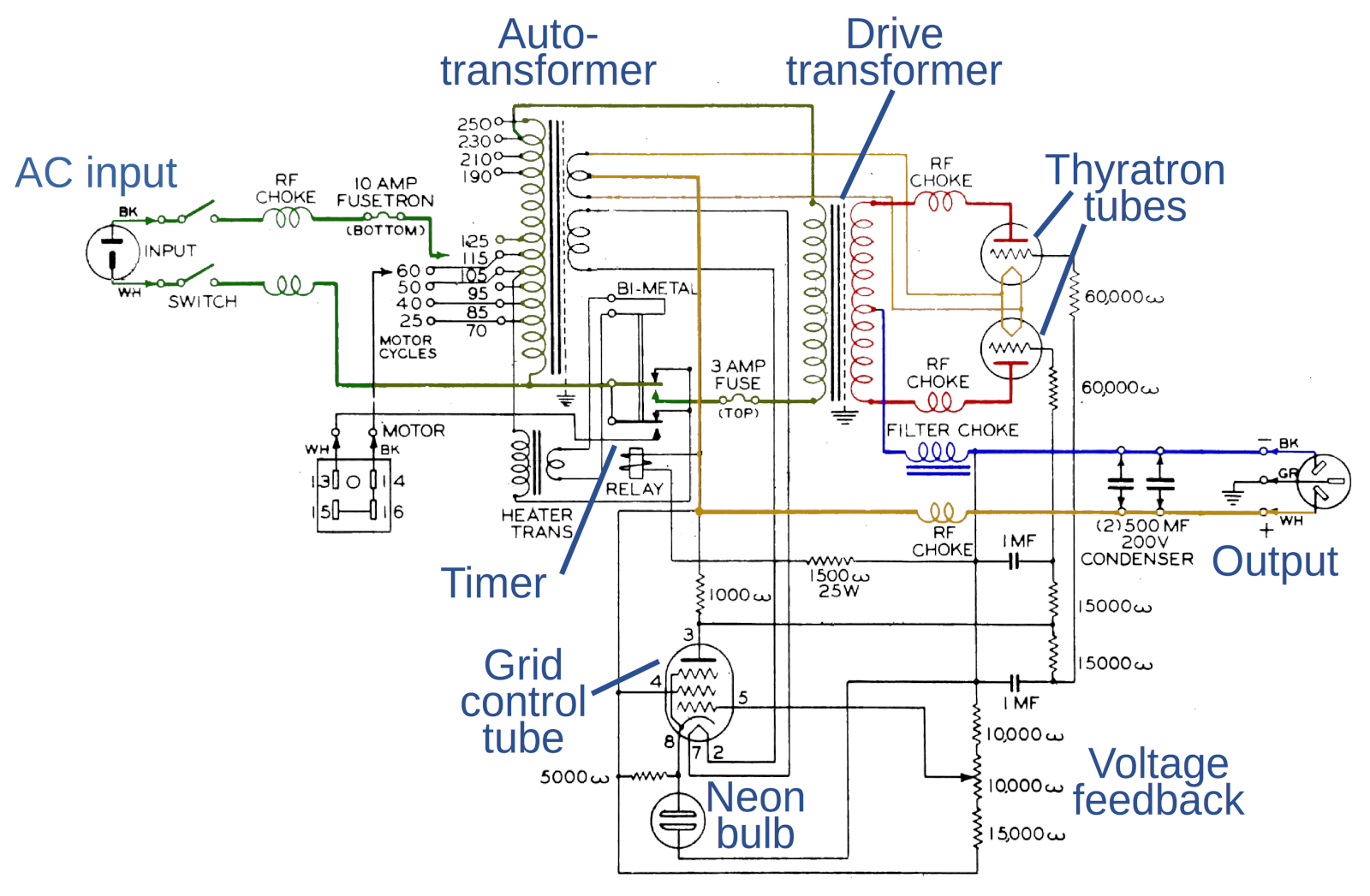
The IBM 704 computer was using a vacuum tubes, mechanical timers and (almost similar to Star Treck-ish, ndr) thyratrons.
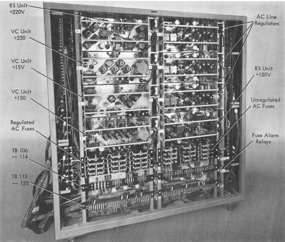
I did not find a DC-DC converter of that period, only off-line SMPS, like the one in the IBM computer.
It was not really common back then the usage of such switchers, up to the advent of semiconductors. Here the scope is not to highlight which design was best, but what technology was used and the complexity that came out of it, tracking it in a chronological order. In fact, the path was going from tubes to transistors, inevitable in the middle ages of electronics, where semiconductors started to be used a bit everywhere.
The middle days (1960 – 1990)
With the advent of semiconductors, the first devices were actually diodes and then transistors. In 1953 went out in the market the first BJTs. Few years later, it became possible to integrate more transistors on the same silicon die: it was the invention of the IC (Integrated Circuit) where the first working prototype was available in 1953, but the first commercial unit was in 1960 from Robert Noyce.
So the result is that in 1953 the first commercial transistor appeared, but in 1960 was the beginning of integrated circuits era. Yet, not for the power supply applications, notorius to be deeply analog. In those days, the manufacturing of ICs was not very precise, with the engineers still relying on discrete transistors for analog application. But it was only around 1964 that the Fairchild uA702 was released, designed by Dave Talber and Robert Widlar. Then the next year the uA709 was ready to make the ground for its successor, still from Widlar when moved to National Semiconductors, the LM101. But at Fairchild in 1968, from Dave Fullagar, the uA741 was finally born.
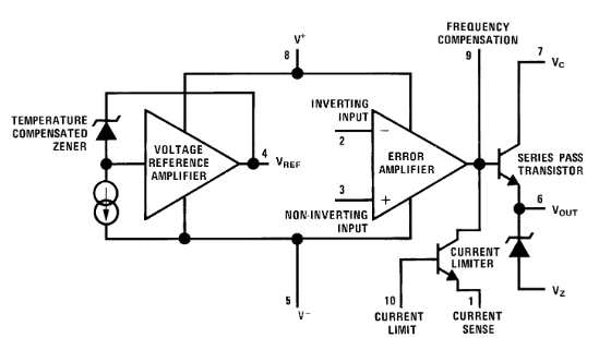
During that period, there were mixed alternatives, with ICs containing references and output drivers, which could be used in many different ways, from LDOs to switching powers supply controllers. A typical example was the uA723:
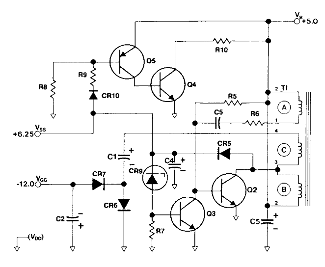
In the switching power supply domain, things are not necessarily linear – pun intended. In fact, in the beginning of the 70’s was still possible to find transistor based power supplies. For example, here a switching power supply, with dual output and protection features, from the HP-97 service manual:
This big improvement on this ICs, alongside the production of better power transistors, led to a development of more complex power supplies which were too complex to design only with transistors. Engineers were using also the NE555 for handling the PWM control required in a switching architecture, and the web is still overfilled by such circuit diagrams. That chip was out there aready in 1972. The 555 can compare, wait, set/reset an output. All key features when you need to compare a voltage, control a switch and be sure you control that in time. The NE555 inside would look like the following block diagram:
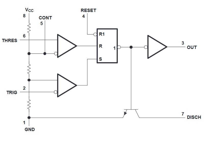
If this 555 is compared with the uA723, it is possible to grasp the feeling of the applications: the 723 having couple of internal amplifiers, one for a reference voltage and an output driver, it can be used also as LDO, driving in an analog manner the output transistor. This cannot be certainly obtained with a 555, which works on 1-bit digital logic, but the switching regulators allows to use anything which contain a reference and an output driver, whether analog or digital.
One of the first PWM controllers IC came out of the market in 1976, with the introduction of the Silicon General SG1524, from the efforts of Bob Mammano:
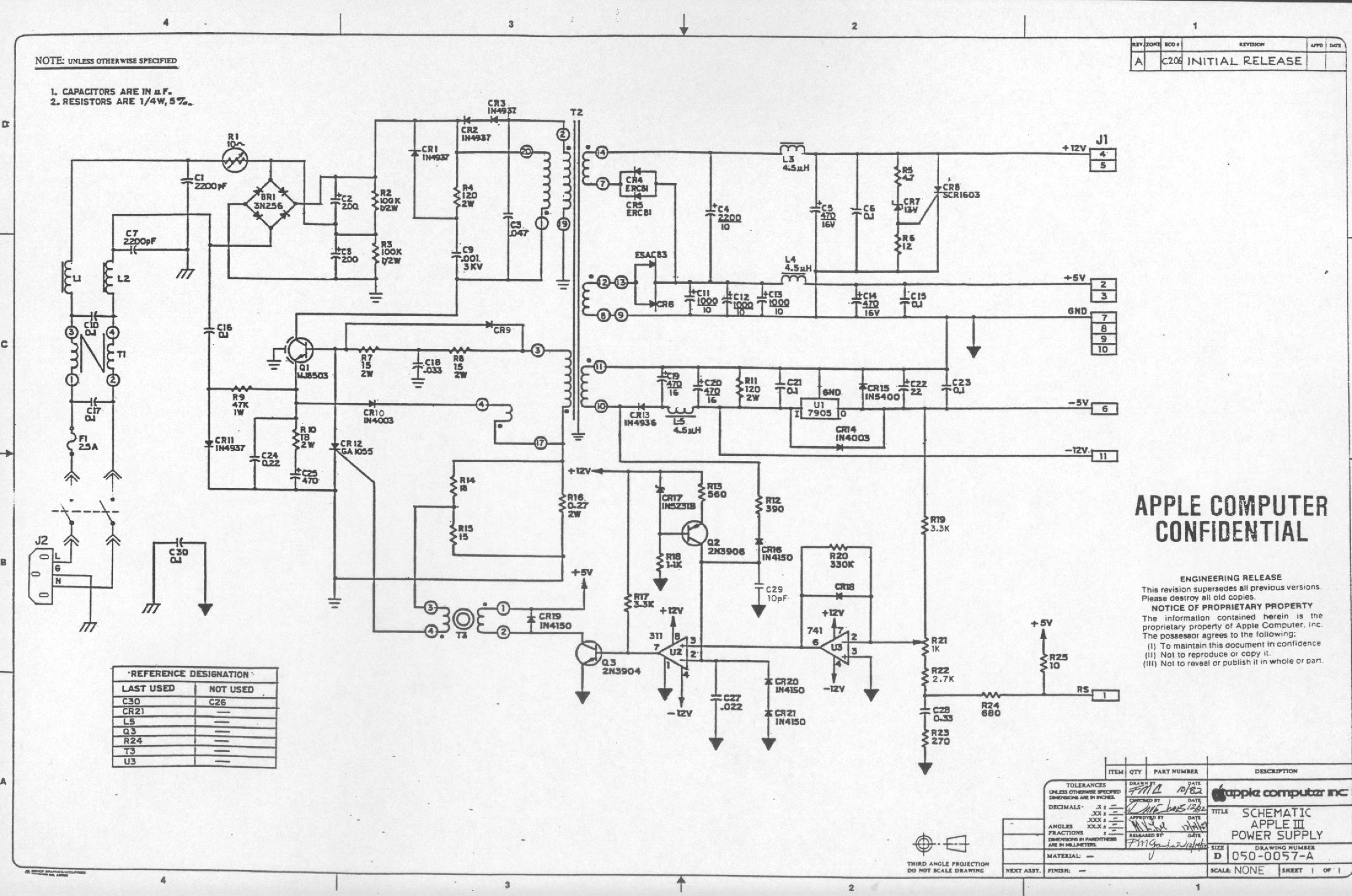
Also, where a controller was not used, before this period, non-specific analog ICs were used instead, providing a middle integration of the technology. A perfect example to show this was the Apple-III power supply, in 1980, using just a couple of op amps: LM741 to sense the output combined with a LM311 to control the switching feedback transistor. Technology does not necessarily follow the market, or maybe, is the other way around.
Interestingly, the Apple II and III were sold among the ’70s and ’80s. I still did not find a convincing answer out there about why these integrated solutions were not used, except the probable reasons of the “if it ain’t broke, don’t fix it“.
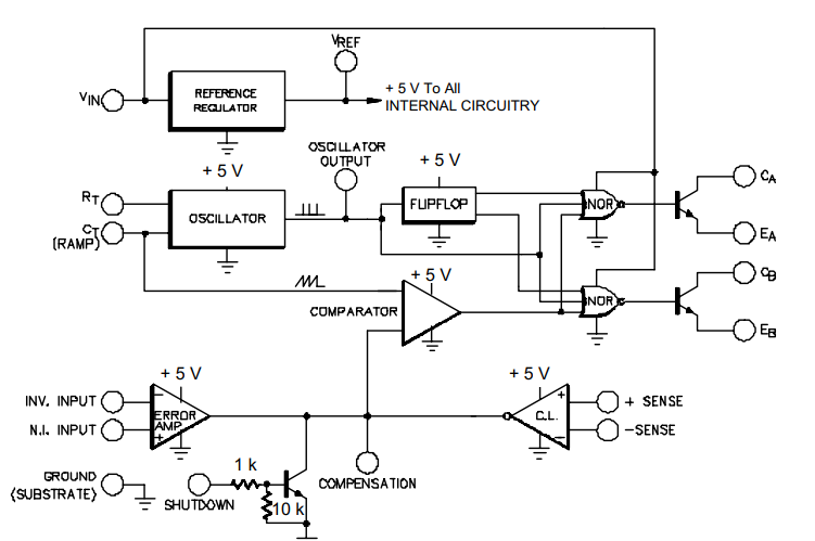
Increasing in the complexity and refinement in the control, with SG1524, the success was guaranteed by an error amplifier for feedback, a shut down input, current limiter, an oscillator providing the pulses and ramps to generate a proper PWM signal and the presence of a reference voltage source. Quite a bit different from the NE555 or the uA723, hence why designers started to use that, as most of the complexity was now integrated. Increasing towards a specific application ICs, this let us understand why the NE555 is used in hundreds of different applications, but a switching regulator circuit only a subset of those applications. Other vendors made then similar outcomes of the 723, like Motorola MC3420, Texas Instruments came out with the TL494, and so on in the integrated PWM controllers era.
Later in the 80s, similar to the SG1524, the MC34060 came out as a lower cost alternative for such controllers. Later, another category enters in the market, lacking the implementation of a constant frequency, called constant on-time variable off-time voltage mode controller, and variations of this concept (for example variable on-time and so on), including the pure histeretic converter. The histeretic converter just contains a comparator (with a reference voltage) and an output driver, is a bang-bang converter, with no timers and hence a self-relaxing system, meaning that when reached the output which triggers the comparator, turns immediately off, and when gets discharged down to another value, turns on. The speed of this cycle is defined by the whole speed of energy transfer in the system.
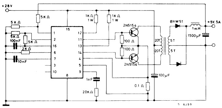
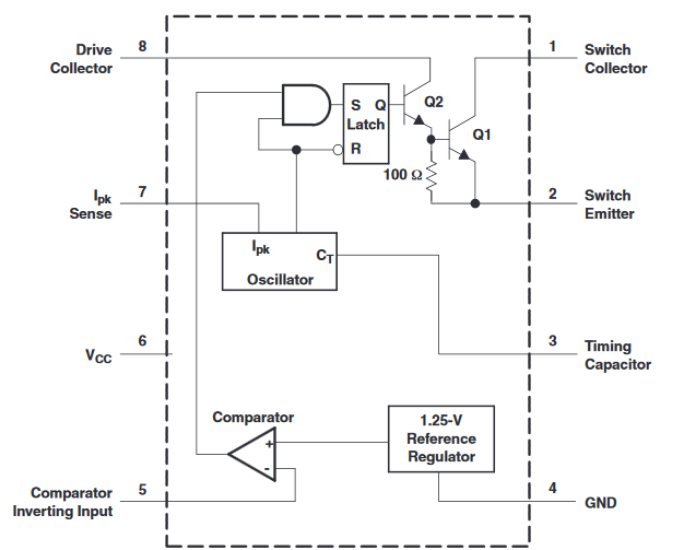
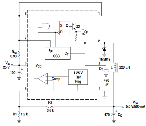
The frequency variability happens because the on-time plus the off-time are defining the switching period. A famous piece of this is the MC34063, released probably in 1983.
Being still sold in 2019, is likely to be considered a jelly bean part of the power supplies. It does not have a fixed frquency, as depends on the load, but the variation is more limited compared to a histeretic topologies, and is very cheap, covering most of the common applications.
Later on, the technology gain its momentum, moving towards providing even more integrated, full featured devices, which is also the trend in the present day.
The modern days (1990 – present day)
Today the technology gets so advanced, at least for simple DC-DC converters, that the industry demands for simplicity gets satisfied more and more. A low count BOM is essential to reduce cost and/or development time. Today are existing fancy solutions, integrating as much as possible, with different flavors, covering automotive requirements and low power demands.
In these years, a typical switching regulator circuit will look like the LM34919, based on the same concept of the LM34063.
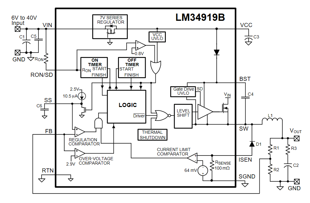
Interestingly, the LM34063 contains 51 active transistors, but on the modern chips now such numbers are loosing value and may not be anymore a market competition element, so are not documented anymore such numbers.
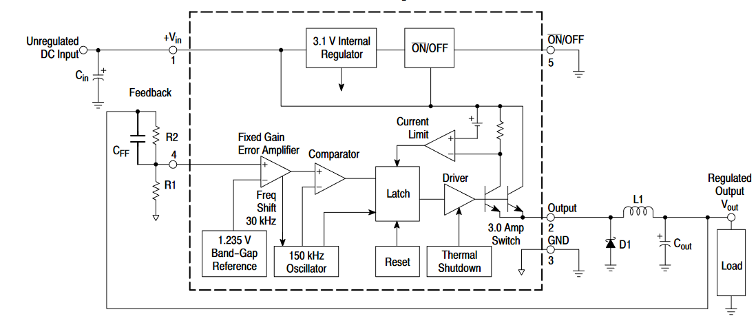
The Constant-On Time regulator, bringing a variable frequency with the input voltage, was known to be cheaper than a modern constant frequency regulator. So since 1980 both constant and variable frequency regualtors, both in current and voltage feedback, were existing, suiting the most nit-picking applications. An example of fixed frequency is the LM2596:
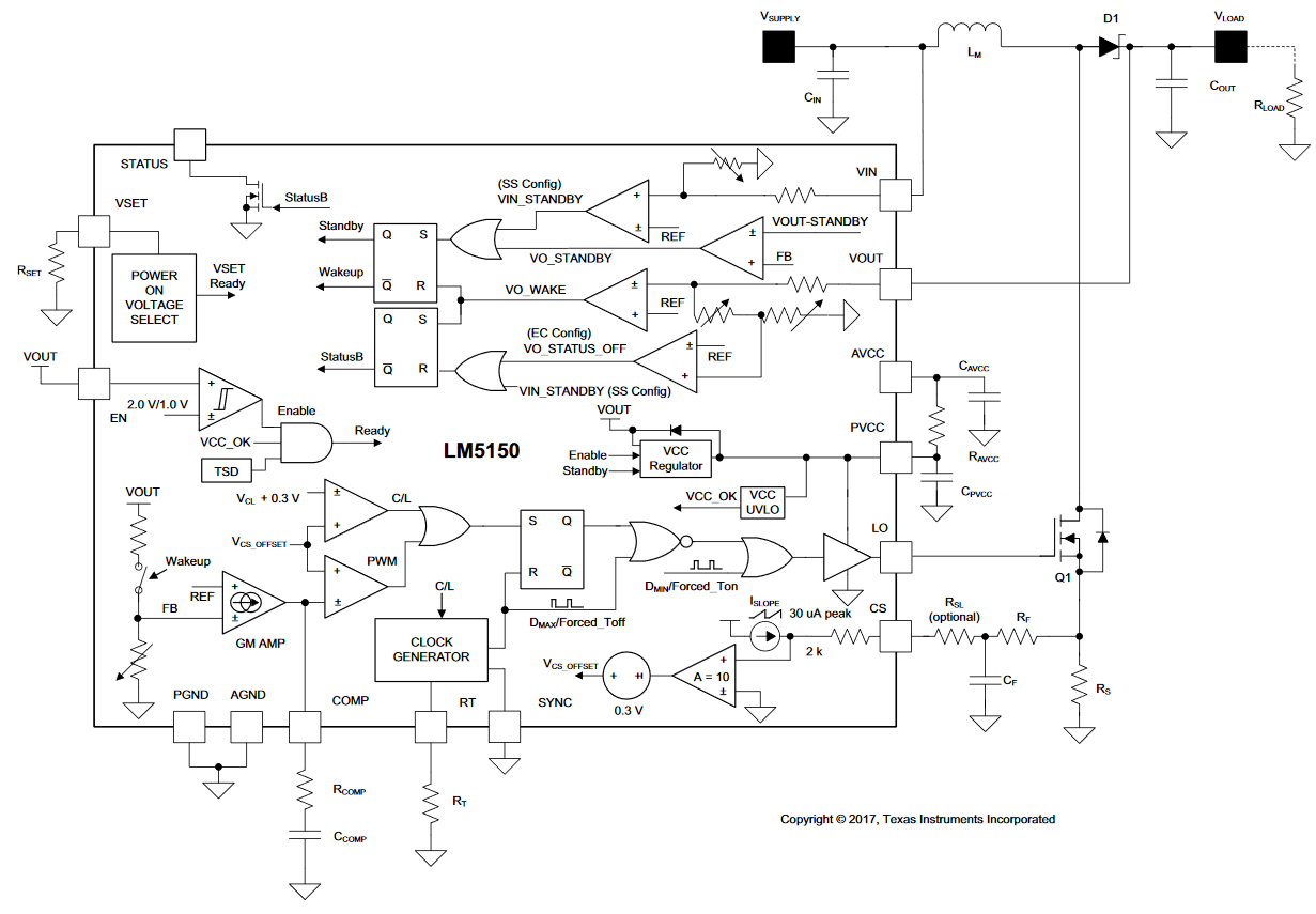
The market now is fully developed with possibilities to synchronize regulators, creating array of them, easy to interface control signals, adjustable frequency and so on, given a cost trade-off.
As if that would no be enough, lazy product designers are asking for DC-DC converters with LDOs design simplicity. Initially the level of integration was limited to the power MOSFET/BJT (like in the LM2596 shown before). But as packaging technology increases, integrating the diode and the inductor became possible, by deploying the systems in package (SiP).
This lead to having integrated literally all the external components; these are commercially called Power Modules. For example, a Maxim part:
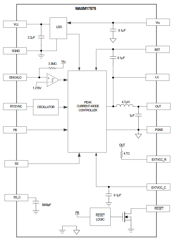
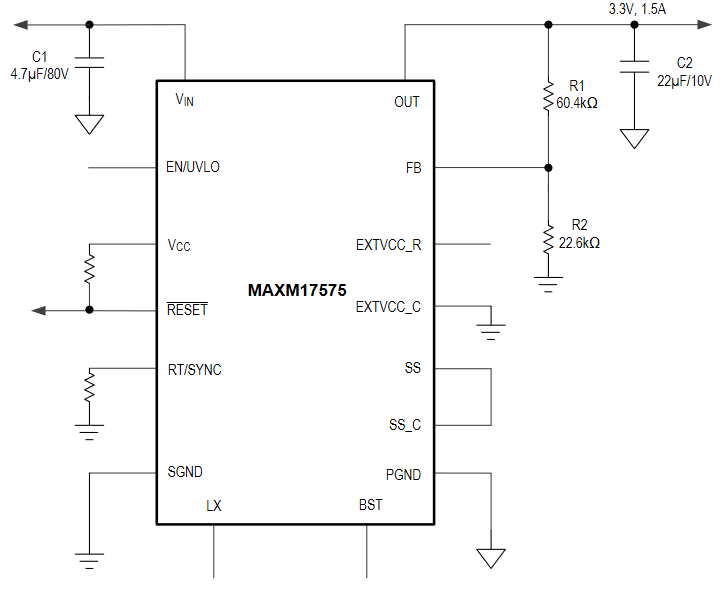
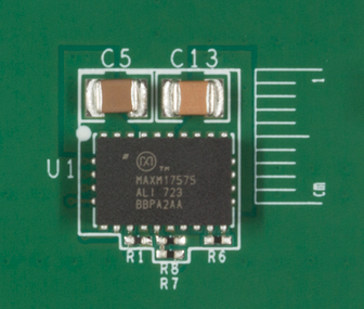
Note how the block diagram does not even contain all the circuitry, as is not relevant anymore, putting all in a box called “<whatever function implemented> Controller”. And is looking sad, when alone on the PCB:
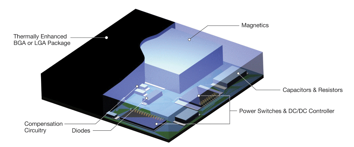
But almost all manufacturers are making now these fully integrated modules with not necessarily an integrated price. From Linear, a nice (but probably not realistic) representation of the module concept:
Now, why we don’t see all of these module around? Acutally, they are used, but only when cost is not an issue in high-end power-hungry digital devices and where a (almost) “first time right” design is a must, because, you know, time to market and design outsourcing speed. In fact, those guys could cost few tens of € or $ per unit, like 10 or 20$ or more, in volume. Because where low BOM count was not selling anymore, the low time-to-market was the new selling strategy from semiconductor companies.
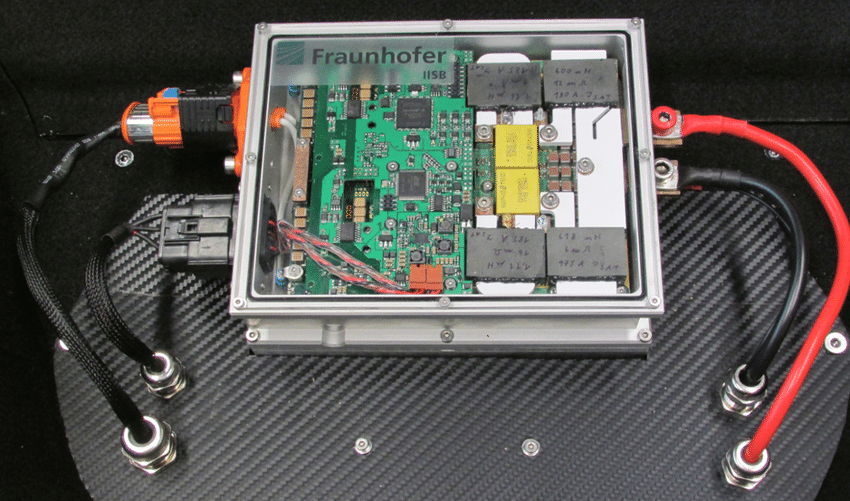
But when used in such FPGA boards, the cost of the converter becomes irrelevant:
And when an FPGA controls a power supply, usage will immediately scale up, in terms of features and experimenting options:
Conclusions
All this butchered brief was related to relatively low power switching converters. While going into higher orders of power magnitude requires a look from a different perspective. But with low power converters (from mW to hundreds of Watts), is possible to focus all the integration and technology into the controller, which can well be a monolithic circuit, like the MC34063, shown here with a real picture of its die:

Discovering the history behind makes us appreciate a bit more the effort put to produce such “simple” ICs. Going towards power conversion efficiency, which does not always mean increasing in complexity, but means also going just complex enough to have something working, or something really compact if the market demands that.
