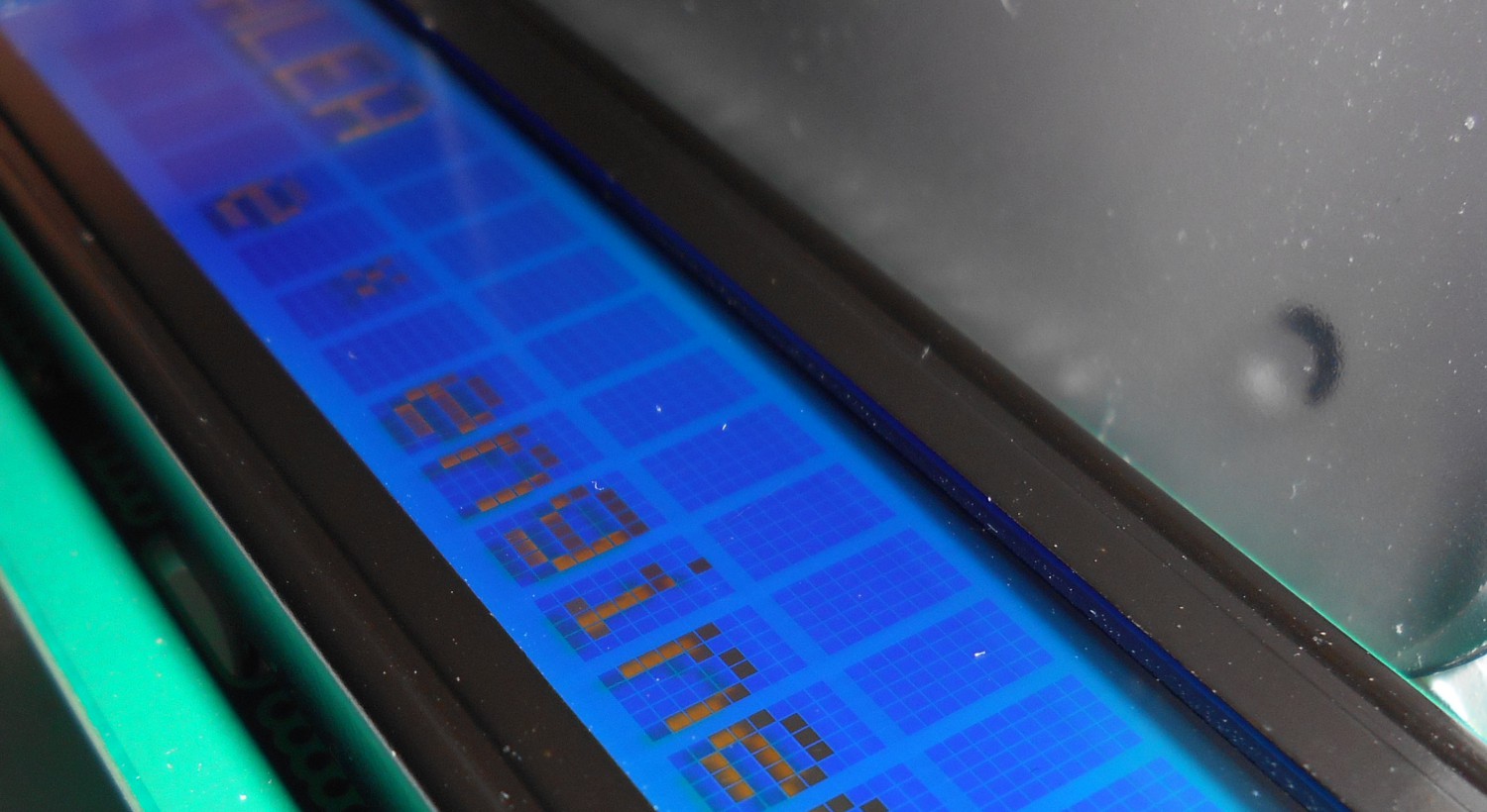
I’ve received one of those (supposedly) Chinese powerful LED torches from my brother. To be precise, this one:

I was not expecting too much from it, it’s awesome and does a lot of light and the like. But I do not want to praise it, rather I got very suspicious when I’ve discovered that contains a Li-Ion 18650 battery, among the option to use normal 3x AAA. I started to think that my brother which gave me this, in reality wanted me died. But to be sure, I had to find proofs by dismantling the charging circuitries.

The legit Li-Ion battery 
The (also) legit 3x AAA alkaline alternative
After checking and get a confirmation in the video by DiodeGoneWild (a must watch!) the torch can be charged with DIRECT connection of the Li-Ion wall charge to the cell. So, with the alkaline is not nice as they are not rechargeable, but with a Li-Ion cell is even worse, as the charger shows this a spec of 4.2V +/- 0.5V. But a Li-Ion cell can be charged up to 4.2V +/- 0.001V – and that’s already border-line.
The output voltage was in fact 4.43V. Is within specs (of the charger), but of course this WILL BLOW UP the Li-Ion cell. Unless the cell has internal protection. The Li-Ion cell is a rebranded Melchioni, under the model number 491463537, “documented” here. Is in italian, but essentially states that is just an unprotected cell. Aside of the charger, the cell is legit, as it was added after the import. Just to report the content of the link here:
Batteria 3,7v modello consumer con celle agli ioni di litio, ricaricabile, senza protezione, […] maneggiare con cura va caricata ad una tensione di 4,2v, 4,3v massimi, una tensione ulteriore la renderebbe pericolosamente soggetta ad esplosione […]
una scheda a circuito stampato di protezione è necessaria […]
i clienti devono sapere come gestire le fasi di carica, scarica e assemblaggio delle batterie agli ioni di litio prima del loro utilizzo.
Which translates to, fundamentally:
1. Cell without protection, charge up to 4.3V otherwise it might explode
2. Use a protection circuit
3. The customers shall know how to handle charge, discharge before their usage.
TL;DR None of these 3 points is matched, as you can read in the following part of this article. My brother wanted to kill me.
The analysis
Maybe I am too skeptical, as this charger could provide the charging protection, but my feeling says is just a crappy constant voltage source. So I got the freedom to disassemble the charger, and differently from DiodeGoneWild (https://www.youtube.com/watch?v=xdAxWei_v3Y), this does not even have a an optical feedback and few other cost reductions. It seems to be a “classic” Ringing Choke Converter power supply, lethal edition. Some nice and simple description of them can be found here. A reverse engineering effort reveals its structure:
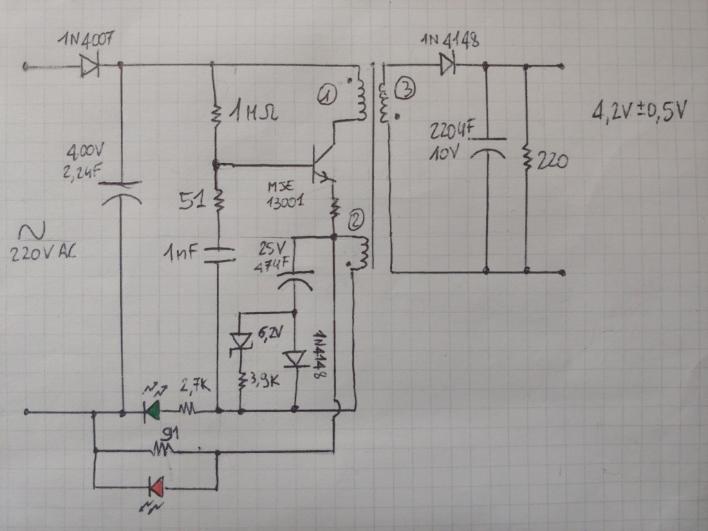
When I tried it, the green LED seemed always on while the red LED was lit only when enough current is put at the output. The approximate mechanism of this converter seems that while the winding 1 has a positive polarity on the dot, same happens on 2 and 3. This mechanism is started via the 1MΩ resistor, which slightly turns on the MSE13001 BJT. The winding 3 is blocked by the diode, while the winding 2 will inject current in the base through the 1nF and 51Ω network to put the BJT into saturation, fully turning it on and will also likely turn on the green LED. The green LED and base peak voltage regulation is made via the 6.2V zener diode.
As the current in winding 1 stops to increase and the 1nF capacitor gets charged, all the polarities gets neutral, the BJT allows lesser current, so the winding 1 will decrease. So the polarities of the other windings gets reversed and energy is transferred from the winding 1 to the 3 and the output reaches a rectified voltage. The reversed voltage also apply on the winding 2, keeping the 1nF discharged and the BJT fully off. Now conceptually butchered down, the more output energy is needed, the longer the windings stays reversed, because more energy needs to be stored in the winding 1. So the longer the off period lasts, the longer the winding 2 is reversed and provides a drop on the 91Ω resistor, keeping the red LED on. In this way, when there is enough output power provided, the charger will be red/yellowish, otherwise is green.
First element of a cost reduction is the usage of just a 1N4007 diode acting as half-bridge rectifier. The next one, the PCB trace as fuse, which does not look weak enough to safely blow – explosion tests later in the article! The next element of cost reduction is…. EVERYTHING. Why am I even take this design seriously.

Given the dangerous output specification because of the precision needed, is slighty otrageous they have used a primary regulation, as this approach cannot guarantee tight tolerances by design. But this is not the worse, as we have not checked the layout yet:

The broken insulation 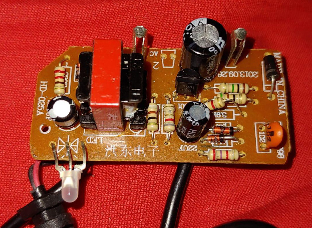
The insulation shall be giaranteed also by a more expensive safety transformer. Is it the case? LOL
Essentially the LED directly connected to one terminal of the AC line, just next to the output connector, which is soldered with thin wires as well. Regarding the PCB insulation, what is the point of keeping an isolation of then gets broken as shown in the above picture?
Also, the silk seems random a well, because they reversed the + and – signs. Probably, they reversed also the concept of electricity and human life as well.
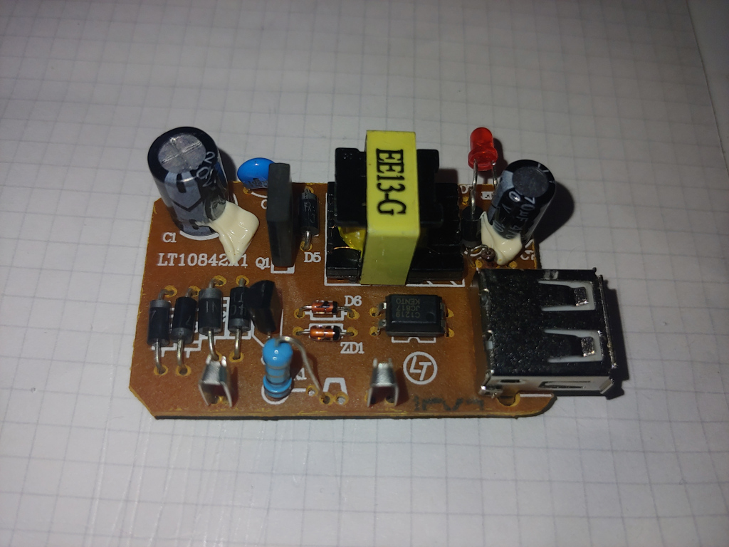
The plastic case used to hold it is a standard mold wall-plug used also by other manufactures. Because of the standard form-factor, are very cheap:

By the way, both of chargers in this pictures has a fake CE mark. Except this, by comparison, the other charger of the same form factor, has a design which looks a little bit more capable to provide good tolerances (and is a USB output type, hence it can have a lot less precision!), with proper separation, full bridge rectifier, optical feedback from the secondary and probably a resistor used as a fuse element. Oh, the the LED is on the secondary side. Secondary side.
Should we write that in Chinese? 将LED放在次级绝缘侧!

What is also interesting is that I read somewhere these chargers are around because the original Ringing Choke Converter patent was expired.
The verdict
In conclusion, I tossed the charger (with proper eco disposal!) and kept the case for a potential project. Being myself a low-power engineer, I will probably fit inside an off the shelf AC/DC (keep rockin’) converter, to power some custom design I might think of. Also, as a rule of thumb, is always better to pay something more to avoid financing illegal and dangerous habits.
